DLPU109A May 2021 – September 2024
3.1.3 Powering-up the DLPC7540EVM and Preparing to Program the DLPC7540EVM
There is only one jumper that is included with the DLPC7540EVM. This jumper is installed on J67 during normal operation between formatter and front-end boards. Before powering up the EVM for programming, make sure the included jumper is installed on J9 instead. The jumper locations are listed in Section 2.2.1.
| Jumper | Description (Bold Indicates Default Position) |
|---|---|
| J67 - Front End 5V | Uninstalled - 5V not supplied to J3 Installed - Formatter board provides 5V to Front-end board over J3 connection |
| J9 - Hold in Boot Loader | Uninstalled - Normal Operation Installed - Hold in Boot Loader |
Jumper J9 is the Hold BL jumper. This jumper is used to put the DLPC7540EVM into boot loader mode, which allows the DLPC7540 controller to be programmed. Connect this jumper to prepare the DLPC7540EVM to be programmed.
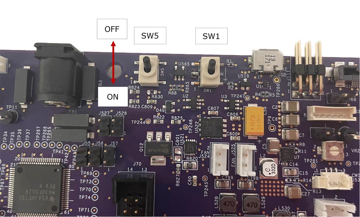
To power up the DLPC7540EVM, a 12V, 5A power supply is needed. Make sure the power supply is functional and the switch SW5 and SW1 on the formatter board are set to off before connecting the power supply to the EVM. Connecting the power supply when the switch is in the off position can prevent damage to the DLPC7540EVM from poor power connections. The image below shows SW5 and SW1 and the operating positions.
 Figure 3-2 ON/OFF Switches
Once the power supply has been connected to the DLPC7540EVM, the switches SW5 and SW1 in that order can be flipped to the on position. Users can then plug in the USB cable to J2 of the board to prepare for programming the board. Verify that D5, D6, D7 and D15 LEDs are on.