DLPU131A November 2023 – September 2024
4 Appendix
- Program MSPM0 Controller
- Items needed (*not
included with EVM)
- XDS110 Debug Probe (TMDSEMU110-U) kit (with included cables & adapters) or LP-XDS110 and 10-pin 2x5 Socket 1.27mm IDC (SWD) cable, purchased separately.*
- TI UniFlash programming application.*
- MSPM0 software or programming file.*
- EVM UUT
- 5V Power supply for EVM.*
- Computer.*
- If using the XDS110 Debug Probe, then connect to the computer with USB cable (USB-A to Micro USB cable included in kit).
- Connect the 20-pin debug cable to 20-pin debug header on the XDS110 Debug Probe.
- Connect the ARM® Cortex®-M 10-pin (CM10) adapter to the other end of the debug cable.
- Connect the CM10 adapter
to J1 on the EVM (MSPM0 ARM® SWD connector).Note: See example of LP-XDS110 and XDS110 Debug Probe Assembly in Figure 4-1, Figure 4-2, and Figure 4-3.
- Connect power supply to board.
- Turn on power to board.
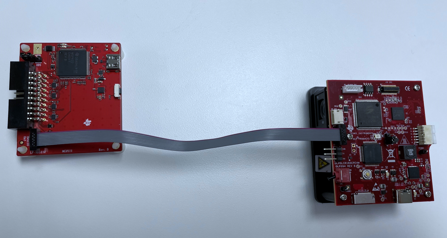 Figure 4-1 LP-XDS110 Debug Probe
and EVM
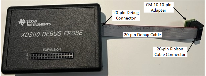
Figure 4-2 XDS110 Debug Probe Assembly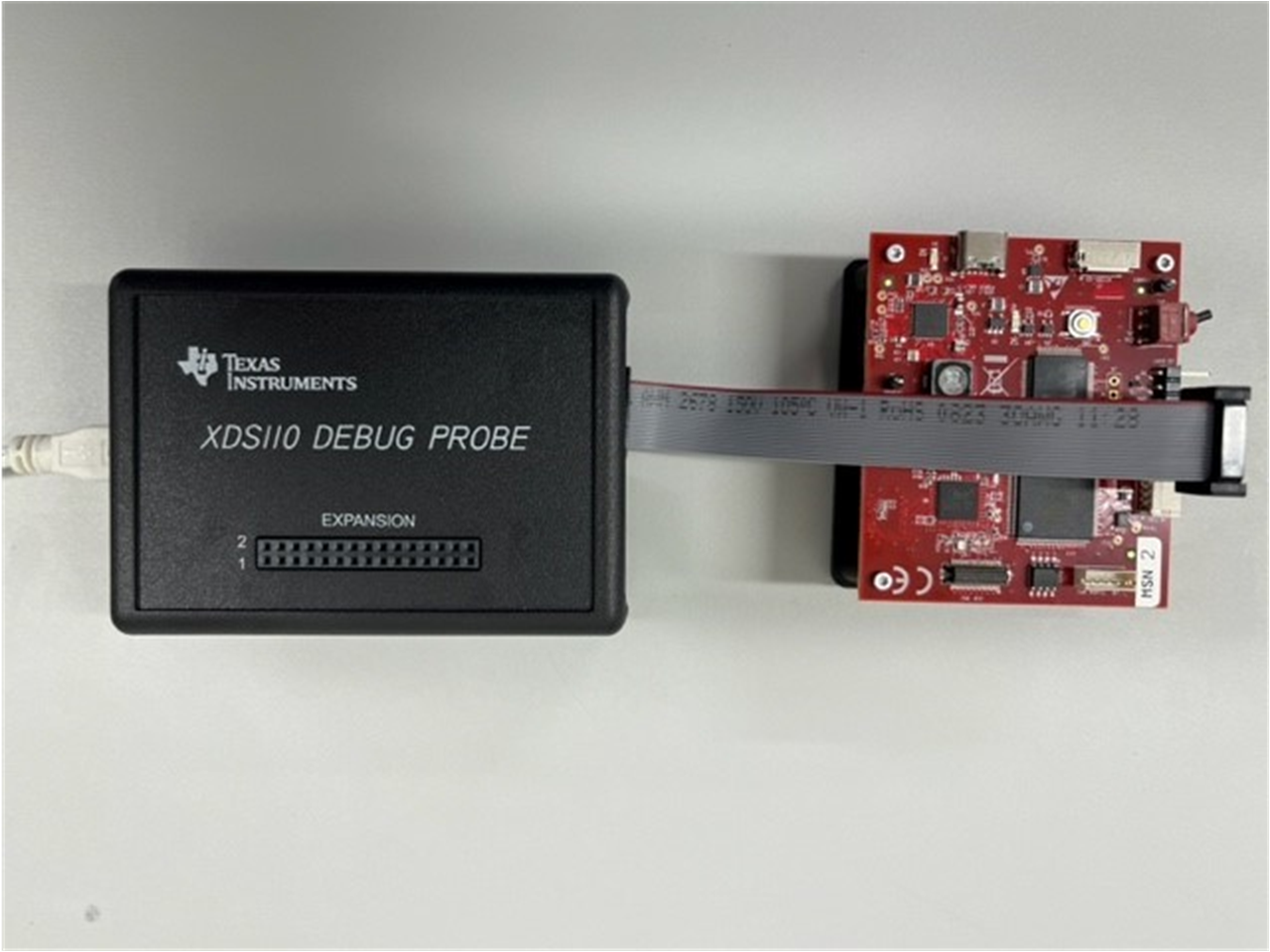 Figure 4-3 XDS110 Debug Probe and
Board Assembly
 - Items needed (*not
included with EVM)
- UniFlash Programming
- Download and install the TI UniFlash flash programming tool (version 8.4.0 or later) from TI.com at https://www.ti.com/tool/UNIFLASH.
- Launch the
UniFlash.exeNote:
The XDS110 firmware must be updated to v3.0.0.26 (or newer) to support the MSPM0 devices. The XDS firmware can be updated using the UNIFLASH programming tool.
- In the New Configuration
tab, select the MSPM0G3507 device, and Texas Instruments
XDS110 USB Debug Probe connection:
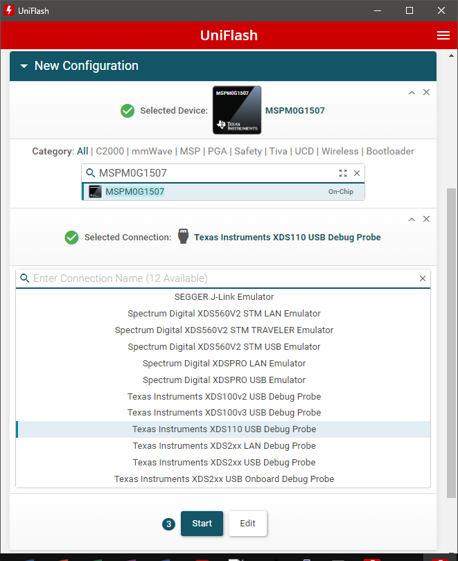
- Click the Start button.
- Browse for and select the
DLPDLCR160CPEVM_RevE19.out (or later) image.

- Click the Load
image button, and wait for the Load Program routine to
complete.

- Once the Load is completed successfully, click the Verify Image
button.
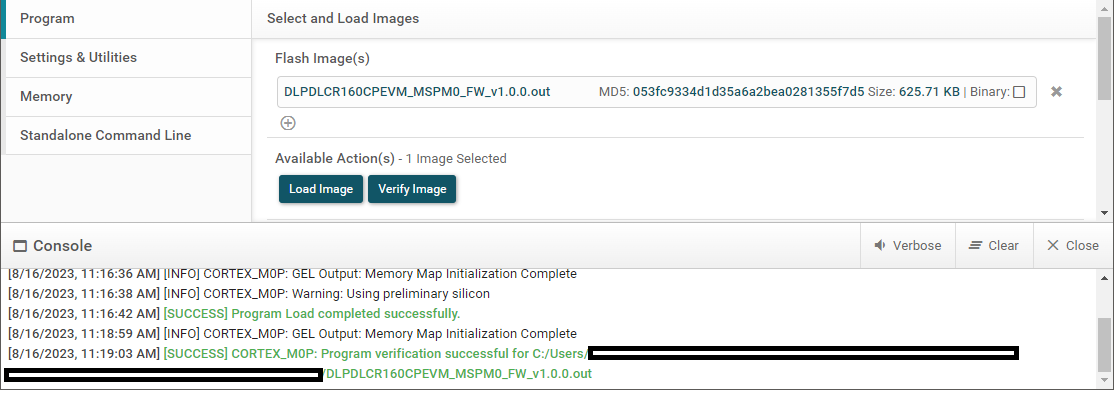
- If the verification is reported successful in the Console, then the flash programming of the MSPM0 is complete. If verification fails, then recheck setup and connections and retry programming.
- Procedure complete.
- Power down and disconnect cables.
- References:
- XDS110 Debug Probe User’s Guide (SPRUI94).
- XDS110 web page, www.ti.com/xds110.