DLPU137 April 2024
- 1
- Description
- Features
- Applications
- 5
- 1Evaluation Module Overview
- 2Hardware
- 3Software
- 4Hardware Design Files
- 5Additional Information
3.3.1 Kit Assembly Instructions - DLP4621Q1EVM
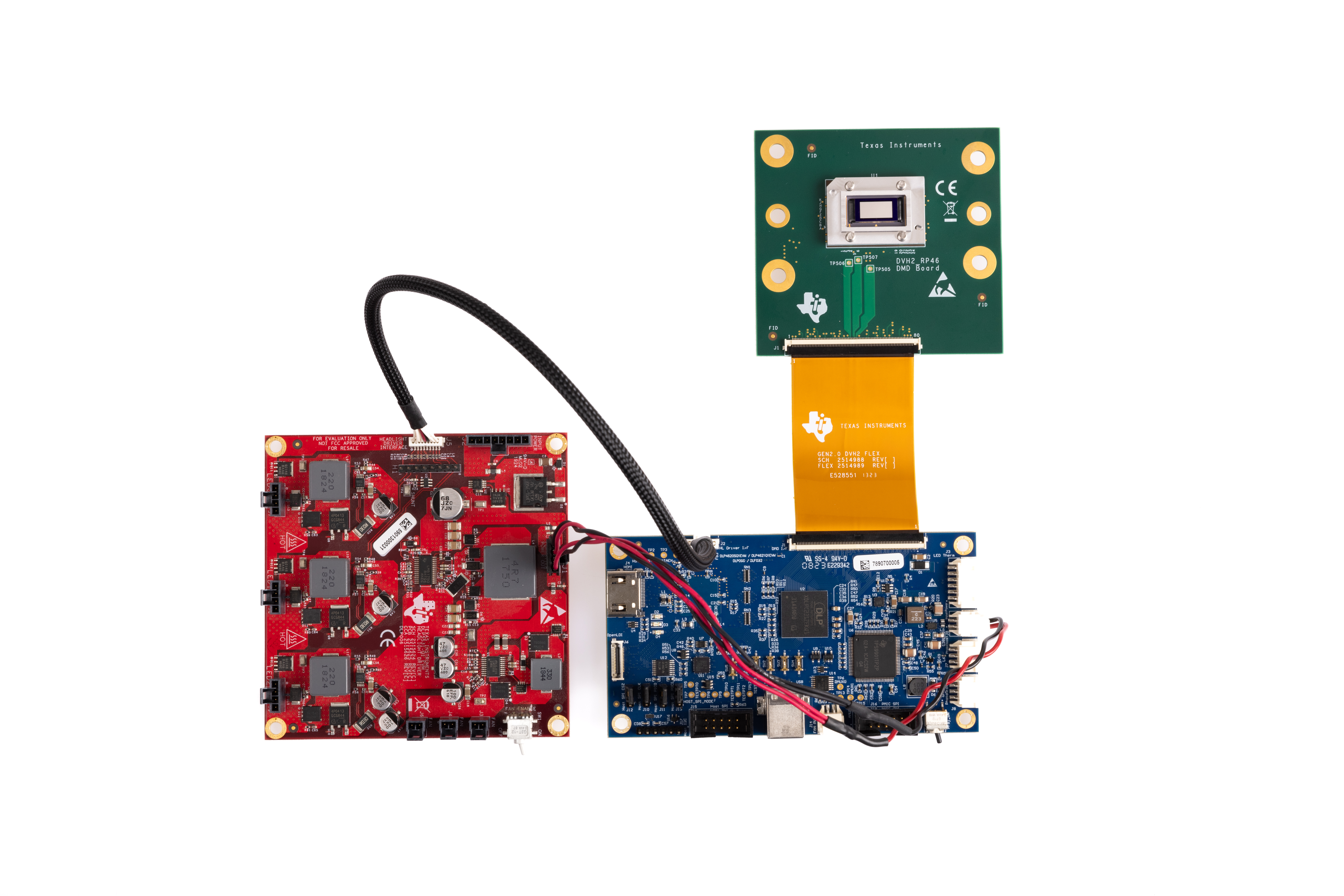
An example image of the DLP4620SQ1EVM without a power supply and optics is shown in Figure 4-10.
- Connect the DMD Flex Cable to the controller PCB (J1) and the DMD PCB (J1). Pin 1 is marked on the DMD flex cable. Make sure the controller side of the flex cable is aligned with the controller PCB.
- Connect the controller to driver control interface flex to the controller PCB (J2) and the illumination driver (J5).
- Connect your host communication cable to the controller PCB and your
host computer.
- If using the Total Phase Cheetah SPI Adapter, follow the jumper configuration found in Section 3.4.
- If using a direct USB connection, follow the jumper configuration found in Section 3.5.
- Connect the controller power cable to the controller PCB (J2) and the illumination driver (J1).
- Connect the LED power cable to any of the LED Driver Board LED ports (J7, J8, J9). Note that some ports can be disabled by flash setting. LED0 (J7) is in the ON position.
- Connect the Fan Power cable to any of the illumination driver fan ports (J3, J5, J6). Confirm the fan switch on the illumination driver (SW1) is in the ON position.
- Connect the micro HDMI cable to the controller board (J4). Connect the micro HDMI cable to the PC HDMI port.
- Connect the Power Input cable to the illumination driver (J2).
 Figure 3-2 DLP4621Q1EVM EVM Cable Connections
A.
If communicating with the controller, then be sure to always check what the jumper configuration is. Jumpers J10, J11, J12, and J13 determine whether or not the controller recognizes SPI or USB communication.