SBAA288A July 2018 – January 2019 ADS7142
5.3 Autonomous Mode With Post-Alert
In autonomous mode with post alert data, the ADS7142 captures the 16 conversion results after the alert is activated. Figure 20 shows the filling of the data buffer in autonomous mode with post alert data.
 Figure 20. Post Alert Data for Dual-Channel Configuration
 The main routine for this functional mode is the following:
#include "ADS7142RegisterMap.h"

/*
ADS7142_AutonomousMode_PostAlert_AutoSequencing_CH0_CH1_Scan.c
*/

int main(void)
{

//Initialize the master MCU (0 = 100 kHz SCL, 1 = 400 kHz SCL)
TM4C1294Init(0);

//Calibrate out the offset from the ADS7142
ADS7142Calibrate();

//Let's put the ADS7142 into Autonomous Mode with both Channels enabled in Single-Ended Configuration

//Select the channel input configuration
ADS7142SingleRegisterWrite(ADS7142_REG_CHANNEL_INPUT_CFG, ADS7142_VAL_CHANNEL_INPUT_CFG_2_CHANNEL_SINGLE_ENDED);

//Confirm the input channel configuration
uint32_t channelconfig;
ADS7142SingleRegisterRead(ADS7142_REG_CHANNEL_INPUT_CFG, &channelconfig);

//Select the operation mode of the device
ADS7142SingleRegisterWrite(ADS7142_REG_OPMODE_SEL, ADS7142_VAL_OPMODE_SEL_AUTONOMOUS_MONITORING_MODE);

//Confirm the operation mode selection
uint32_t opmodeselconfig;
ADS7142SingleRegisterRead(ADS7142_REG_OPMODE_SEL, &opmodeselconfig);

//Set the I2C Mode to High Speed (optional)
//ADS7142HighSpeedEnable(ADS7142_VAL_OPMODE_I2CMODE_HS_1);

//Check the I2C Mode Status
uint32_t opmodei2cconfig;
ADS7142SingleRegisterRead(ADS7142_REG_OPMODE_I2CMODE_STATUS, &opmodei2cconfig);

//Select both channels for AUTO Sequencing
ADS7142SingleRegisterWrite(ADS7142_REG_AUTO_SEQ_CHEN, ADS7142_VAL_AUTO_SEQ_CHENAUTO_SEQ_CH0_CH1);

//Confirm Auto Sequencing is enabled
uint32_t autoseqchenconfig;
ADS7142SingleRegisterRead(ADS7142_REG_AUTO_SEQ_CHEN, &autoseqchenconfig);

//Select the Low Power or High Speed Oscillator
ADS7142SingleRegisterWrite(ADS7142_REG_OSC_SEL, ADS7142_VAL_OSC_SEL_HSZ_HSO);

//Confirm the oscillator selection
uint32_t oscconfig;
ADS7142SingleRegisterRead(ADS7142_REG_OSC_SEL, &oscconfig);

//Set the minimum nCLK value for one conversion to maximize sampling speed
ADS7142SingleRegisterWrite(ADS7142_REG_nCLK_SEL, 21);

//Confirm the nCLK selection
 uint32_t nCLKconfig;
ADS7142SingleRegisterRead(ADS7142_REG_nCLK_SEL, &nCLKconfig);

//Select the Data Buffer output data Configuration
ADS7142SingleRegisterWrite(ADS7142_REG_DOUT_FORMAT_CFG, ADS7142_VAL_DOUT_FORMAT_CFG_DOUT_FORMAT2);

//Select the Data Buffer opmode for Post-Alert mode
ADS7142SingleRegisterWrite(ADS7142_REG_DATA_BUFFER_OPMODE, ADS7142_VAL_DATA_BUFFER_STARTSTOP_CNTRL_POSTALERT);

//Configure CH0 High Threshold MSB
ADS7142SingleRegisterWrite(ADS7142_REG_DWC_HTH_CH0_MSB, 0x90);

//Configure CH0 High Threshold LSB
ADS7142SingleRegisterWrite(ADS7142_REG_DWC_HTH_CH0_LSB, 0x00);

//Configure CH0 Low Threshold MSB
ADS7142SingleRegisterWrite(ADS7142_REG_DWC_LTH_CH0_MSB, 0x00);

//Configure CH0 Low Threshold LSB
ADS7142SingleRegisterWrite(ADS7142_REG_DWC_LTH_CH0_LSB, 0x00);

//Set the Hysteresis for CH0
ADS7142SingleRegisterWrite(ADS7142_REG_DWC_HYS_CH0, 0x00);

//Configure CH1 High Threshold MSB
ADS7142SingleRegisterWrite(ADS7142_REG_DWC_HTH_CH1_MSB, 0xE0);

//Configure CH1 High Threshold LSB
ADS7142SingleRegisterWrite(ADS7142_REG_DWC_HTH_CH1_LSB, 0x00);

//Configure CH1 Low Threshold MSB
ADS7142SingleRegisterWrite(ADS7142_REG_DWC_LTH_CH1_MSB, 0x00);

//Configure CH1 Low Threshold LSB
ADS7142SingleRegisterWrite(ADS7142_REG_DWC_LTH_CH1_LSB, 0x00);

//Set the Hysteresis for CH1
ADS7142SingleRegisterWrite(ADS7142_REG_DWC_HYS_CH1, 0x00);

//Enable Alerts
ADS7142SingleRegisterWrite(ADS7142_REG_ALERT_CHEN, ADS7142_VAL_ALERT_EN_CH0_CH1);

//Enable the digital window comparator block
ADS7142SingleRegisterWrite(ADS7142_REG_ALERT_DWC_EN, ADS7142_VAL_ALERT_DWC_BLOCK_ENABLE);

//Set the SEQ_START Bit to begin the sampling sequence
ADS7142SingleRegisterWrite(ADS7142_REG_START_SEQUENCE, ADS7142_VAL_START_SEQUENCE);

//Begin Autonomous Mode Post-Alert operation and Scan both channels 0 and 1

while (1)

{

//Start Scanning CH0 and CH1
//If Alert is set, device stops conversions and filling the data buffer
//Read the latched flags of the Digital Window Comparator
while (ADS7142DataRead_autonomous() < 0);

//Reset the alert flags
ADS7142SingleRegisterWrite(ADS7142_REG_ALERT_HIGH_FLAGS, 0x03);
ADS7142SingleRegisterWrite(ADS7142_REG_ALERT_LOW_FLAGS, 0x03);

//Read the Data Buffer Status uint32_t databufferstatus;
ADS7142SingleRegisterRead(ADS7142_REG_DATA_BUFFER_STATUS, &databufferstatus);

//Read the Data Buffer
while (ADS7142DataRead_count(16) < 0);

//Restart the sequence
ADS7142SingleRegisterWrite(ADS7142_REG_START_SEQUENCE, ADS7142_VAL_START_SEQUENCE);

}

//Return no errors
return 0;

}
Figure 21 shows the channel configuration and selection of the opmode for this ADS7142 functional mode.
 Figure 21. Autonomous Mode Post Alert Dual-Channel Sampling Test Data 1
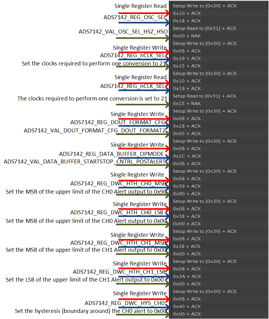
 Figure 22 shows the conversion clock, data buffer configuration, output data format configuration, setting of thresholds for channel 0, and setting of hysteresis for channel 0.
 Figure 22. Autonomous Mode Post Alert Dual-Channel Sampling Test Data 2
 Figure 23 shows the setting of thresholds and hysteresis for channel 1, the enabling of alerts, and the start of the conversion sequence.
 Figure 23. Autonomous Mode Post Alert Dual Channel Sampling Test Data 3
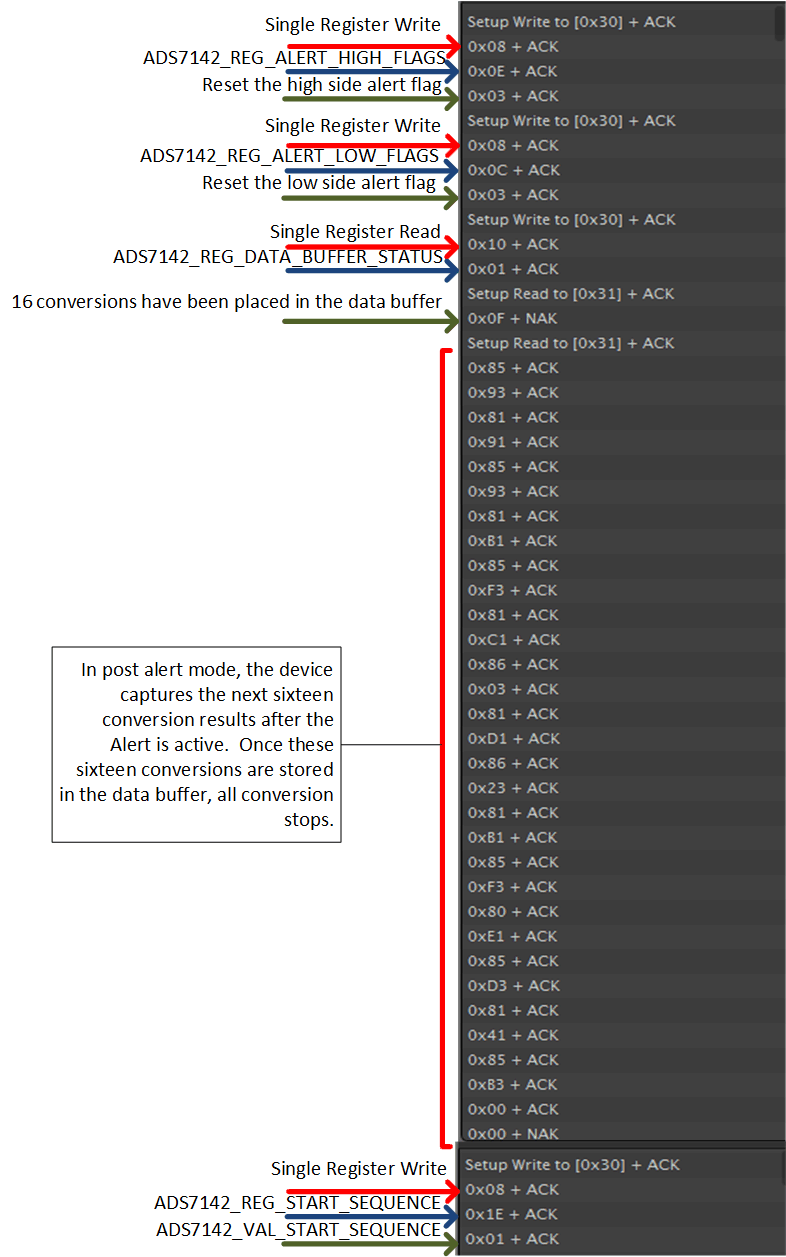
 Figure 24 shows the data results for the alert flag resets, reading of the data buffer status, and clocking out the data inside the data buffer after the alert is triggered.
 Figure 24. Autonomous Mode Post Alert Dual-Channel Sampling Test Data 4