SBAA359B February 2019 – June 2024 AMC1035 , AMC1035-Q1 , AMC1100 , AMC1106E05 , AMC1106M05 , AMC1200 , AMC1200-Q1 , AMC1203 , AMC1204 , AMC1204-Q1 , AMC1210 , AMC1211-Q1 , AMC1300 , AMC1300B-Q1 , AMC1301-Q1 , AMC1302 , AMC1302-Q1 , AMC1303E0510 , AMC1303E0520 , AMC1303E2510 , AMC1303E2520 , AMC1303M0510 , AMC1303M0520 , AMC1303M2510 , AMC1303M2520 , AMC1304L05 , AMC1304L05-Q1 , AMC1304L25 , AMC1304L25-Q1 , AMC1304M05 , AMC1304M05-Q1 , AMC1304M25 , AMC1304M25-Q1 , AMC1305L25 , AMC1305L25-Q1 , AMC1305M05 , AMC1305M05-Q1 , AMC1305M25 , AMC1305M25-Q1 , AMC1306E05 , AMC1306E25 , AMC1306M05 , AMC1306M25 , AMC1311 , AMC1311-Q1 , AMC1336 , AMC1336-Q1 , AMC1411 , AMC3301 , AMC3301-Q1 , AMC3302 , AMC3302-Q1 , AMC3306M05 , AMC3306M25 , AMC3330 , AMC3330-Q1 , AMC3336 , AMC3336-Q1 , ISO121 , ISO122 , ISO124 , ISO224
3 Performance Comparison Between Isolated Amplifiers and Isolated Modulators
Table 3-1 shows the basic difference in performance between isolated amplifiers and isolated modulators.
| CATEGORY | ISOLATED AMPLIFIER | ISOLATED MODULATOR |
|---|---|---|
| Sample resolution | 11 bits (bandwidth = 100 kHz) | > 14 bits achievable, trade-off between resolution and bandwidth or latency |
| Latency | 2 µs to 3 µs (fixed) | < 1 µs achievable, trade-off between resolution and bandwidth or latency |
| Bandwidth | up to 300 kHz | > 1 MHz achievable, trade-off between resolution and bandwidth or latency |
| Accuracy and drift performance | High | Very high |
| No. of components needed | More | Less |
In an isolated-amplifier-based design, the measured analog signal undergoes several analog-to-digital and digital-to-analog conversions. The stages within the isolated amplifier, the differential-to-single-ended stage, and the ADC either external or internal to the MCU or DSP reduce overall accuracy and noise performance and increase latency. The fixed low-pass filter implementation in the output stage of the isolated amplifier limits the signal bandwidth. An external op-amp-based circuit used for differential-to-single-ended conversions can be used to create an active low-pass filter to further limit the signal bandwidth and thereby improve noise performance. The isolated amplifier has a fixed latency. Isolated-amplifier-based designs are widely used because of familiarity and relative ease of implementation.
As shown in Figure 2-1, the measured analog signal in an isolated-modulator-based design undergoes only one analog-to-digital conversion. This design eliminates the need for a differential-to-single-ended stage, thereby reducing the number of components and design size. The ADC used in an isolated-amplifier-based design, which in many situations limits the maximum achievable sample resolution and accuracy, is not needed anymore. This isolated-modulator-based approach has improved signal noise performance, overall accuracy, and can achieve higher signal bandwidth and lower latency than an isolated-amplifier-based design. Isolated modulators provide a much faster digital bitstream output, typically up to 20 MHz. The sigma-delta filter module (SDFM) module inside the microcontroller families (such as the TMS320F2807x and TMS320F2837x) provides an easy way to tune the noise performance and signal bandwidth or latency. As shown in Table 3-2, a higher oversampling ratio (OSR) implementation leads to better accuracy and higher sample resolution but less signal bandwidth and higher latency. Similarly, lowering OSR reduces accuracy and sample resolution but increases bandwidth and reduces latency. A similar DSP or an FPGA can also implement such a digital filter.
| OSR | ENOB (Bits) | SETTLING (µs) | LATENCY (µs) | BANDWIDTH (kHz) |
|---|---|---|---|---|
| 8 | 4.65 | 1.2 | 0.6 | 1250 |
| 16 | 7.57 | 2.4 | 1.2 | 625 |
| 32 | 10.02 | 4.8 | 2.4 | 312.5 |
| 64 | 12.3 | 9.6 | 4.8 | 156.25 |
| 128 | 13.51 | 19.2 | 9.6 | 78.13 |
| 256 | 14.11 | 38.4 | 19.2 | 39.06 |
| 512 | 14.39 | 76.8 | 38.4 | 19.53 |
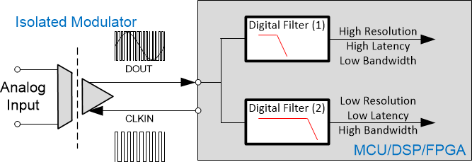
Additionally, as shown in Figure 3-1, multiple digital filters can be implemented in parallel to achieve higher sample resolution, lower latency, and higher bandwidth, all at the same time. One of the digital filters can implement a high OSR digital filter for better noise performance and another one can implement a low-latency digital filter.
 Figure 3-1 Implementation of Two Digital Filter in Parallel
With the system advantages offered by an isolated-modulator-based design, there is a resulting trend to move to an isolated-modulator-based design in high-performance systems.