SBAA449B October 2020 – October 2021 TMAG5110 , TMAG5110-Q1 , TMAG5111 , TMAG5111-Q1
5 Application Implementation
For demonstration, the TMAG5110 sensor with the high-sensitivity option for BOP threshold oriented in the ZX axes was selected to use alongside a 20-pole NeoBond magnet. Each pole therefore occupies 18° of one complete revolution. The magnet was rotated 108° to capture 6 complete pole transition cycles. The expectation when analyzing the output will be that there is a 9° separation between the two outputs.
To start, the sensor was placed centered directly beneath the outer edge of the magnet. The sensor was then stepped radially outward (in the x-direction) from the edge of the magnet in 0.635 mm steps (0.25 mil) to demonstrate the shift in quadrature accuracy and find the ideal air gap with a fixed spacing in the z-direction. This approach was a simpler way to vary the angle in laboratory experimentation as adjustments to a single axis were more practical.
 Figure 5-1 Laboratory Measurement Setup
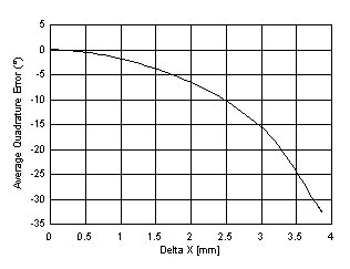
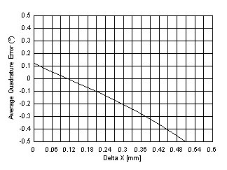
 Figure 5-2 Average Quadrature Error vs Placement
Notice that the quadrature error observed was near its minimum at the start position, but was improved by moving the sensor outward. The results captured show the best location for this setup was approximately 0.11 mm away from the outer face of the magnet. Beyond 3.85 mm, the outputs could no longer properly detect the pole transitions.
In practice, gathering empirical data is a useful alternative to simulation data, and provides a powerful means to confirm simulated expectations. It is important to note that several non-ideal factors are present with this method and help realize the impact of system tolerances on the overall result.
Magnet tilt and wobble, if large enough, will produce shifts in quadrature alignment. One pole transition might occupy 18.2°, while another occupies only 17.8°. Additionally, if the sensor is not completely orthogonal to the B-Field then the sensor might pick up more or less input than anticipated. Another consideration is that each device will demonstrate variations in the exact BOP / BRP thresholds. These threshold shifts will result in small variations in quadrature accuracy.