SBAA510 October 2021 DRV5032 , TMAG5170 , TMAG5231 , TMAG5273
2 Reed Switch Overview
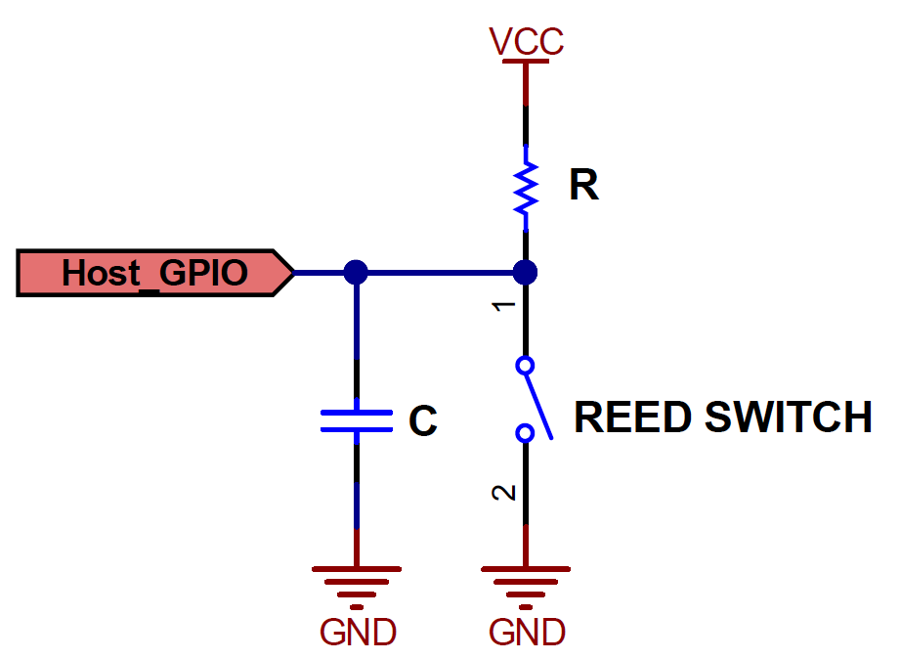
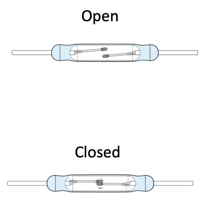
The Reed switch is probably one of the most prevalent components found in today’s door and or window sensor. The switch is essentially a glass tube filled with inert gas with two small blades comprised of some ferromagnetic material. These devices can come in N.O. (normally open) and N.C. (normally closed) configurations, but for much of the building security industry, the normally open contacts are the most popular choice. A common Reed switch is shown in Figure 2-1 along with a simple circuit that leverages the switch in a manner suitable for our application.
 |
 |
There are also post-production problems that occur with the use of a Reed switch that can be of concern. One major concern can be the limited lifetime of the Reed Switch. Because of the mechanical nature of this device, the lifetime of the device is limited due to natural wear and tear of the physical switch.
Another issue can be power consumption on the Reed switches depending on the peripheral circuitry used. If the switch is pulled up to a source voltage when the switch is open, there will be a current associated with this pull-up network. In other configurations, there will be a small current through a pull-down or pull-up resistor when the switch is closed. There are however configurations that can be used to minimize this consumption. These are listed below:
- It can be a sampling of the pull-up resistor. This means the voltage the pull-up is tied up to is controllable. Typically, an IO pin turned on for a few µs while another IO checks the voltage across the Reed switch.
- It can also be a more complex circuit using capacitor and other circuitry to avoid constant current consumption.
- It can also be a 3 terminal Reed switch. In that case the power consumption can be 0.