SBAA510 October   2021 DRV5032 , TMAG5170 , TMAG5231 , TMAG5273


  1.   Trademarks
  2. 1Introduction
  3. 2Reed Switch Overview
  4. 3Hall Effect Sensor Overview
  5. 4Performance Comparison
  6. 5DRV5032 Test Setup and Results
    1. 5.1 DRV5032 Test Setup
    2. 5.2 Understanding the Results
    3. 5.3 DRV5032 Test Results
    4. 5.4 Front Approach Results
    5. 5.5 Side Approach
    6. 5.6 Tamper Susceptibility Testing Setup
    7. 5.7 Tamper Susceptibility Test Results
  7. 6Reed Switch Test Setup and Results
    1. 6.1 Reed Switch Test Setup
    2. 6.2 Reed Switch Test Results
    3. 6.3 Front Approach Results
    4. 6.4 Side Approach Results
    5. 6.5 Tamper Susceptibility Testing Setup
    6. 6.6 Reed Switch Tamper Susceptibility Test Results
  8. 7TMAG5170 Test Setup and Results
    1. 7.1 TMAG5170 Test Setup
    2. 7.2 TMAG5170 Test Results
    3. 7.3 TMAG5170 Tamper Susceptibility Testing Setup
    4. 7.4 TMAG5170 Tamper Susceptibility Test Results
  9. 8Summary

TMAG5170 Test Results

Figure 7-5 and Figure 7-6 show the resulting three-axis magnetic response of the TMAG5170 based on both approaches described previously. As shown by the output, the multiple axes remove constraints on magnetic placement allowing off axis placement to be more feasible due to the only importance being strength of field.
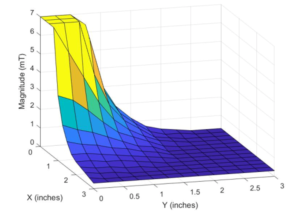
GUID-20210810-SS0I-S1D4-XCT7-DRLDBL410JR9-low.png Figure 7-5 TMAG5170 On-Axis Magnetic Detection
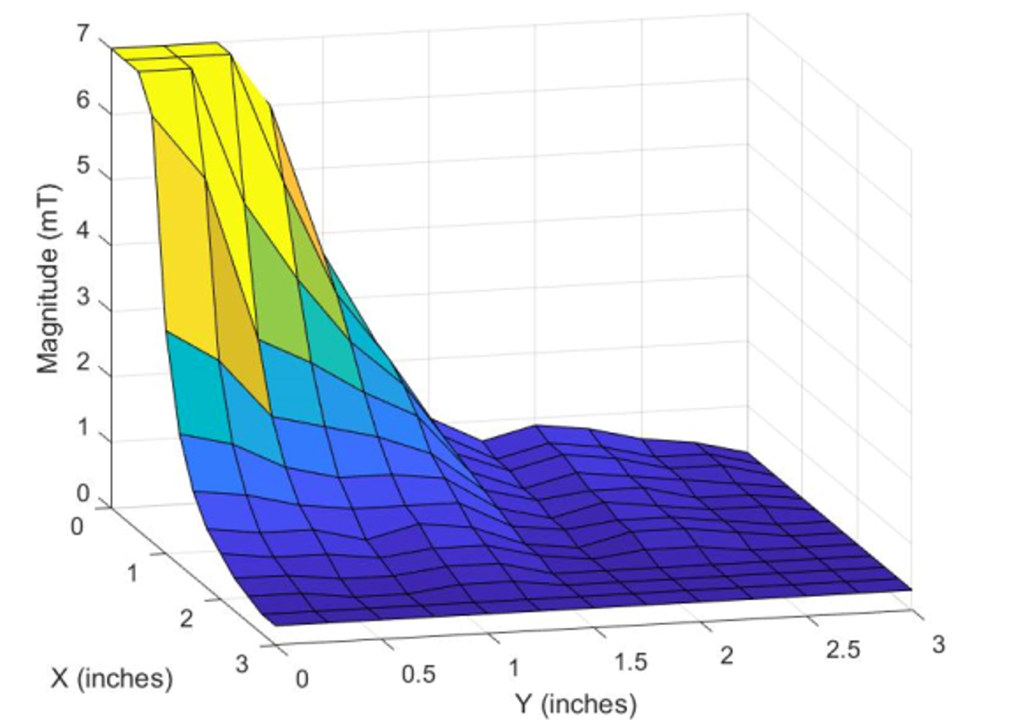
GUID-20210810-SS0I-Q0ZX-VB5X-4LB8LTHJ8JZ0-low.png Figure 7-6 TMAG5170 Off-Axis Magnetic Detection