SBAA510 October 2021 DRV5032 , TMAG5170 , TMAG5231 , TMAG5273
7.4 TMAG5170 Tamper Susceptibility Test Results
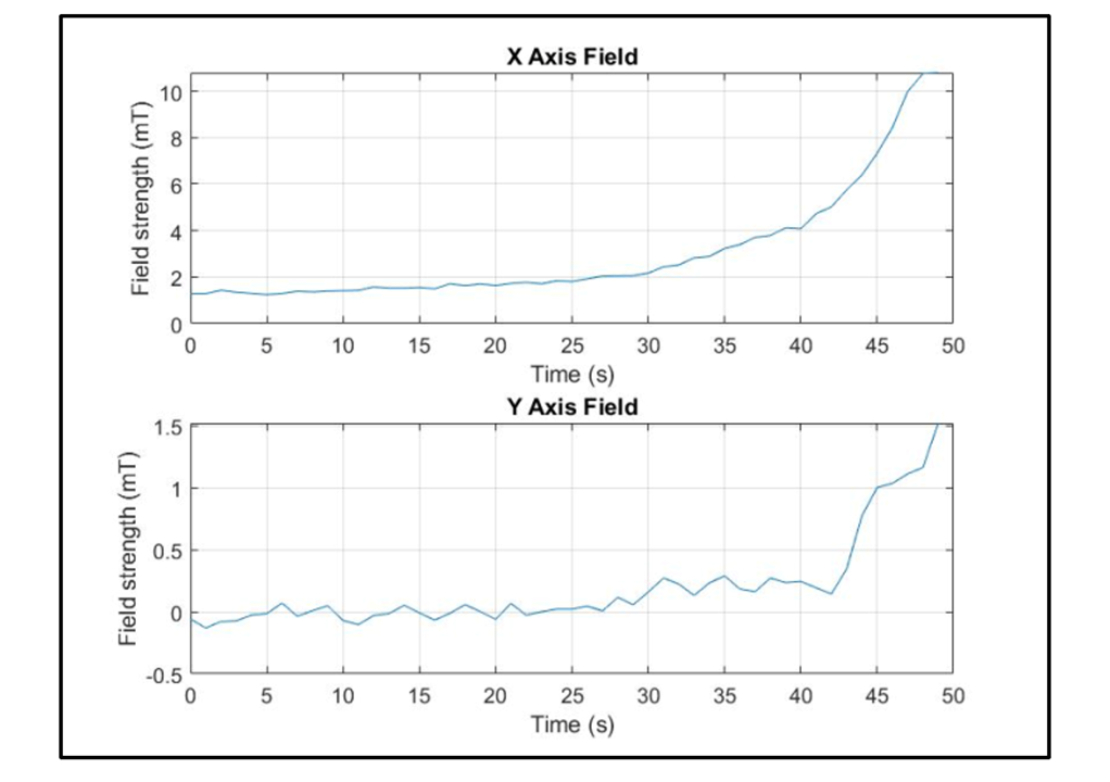
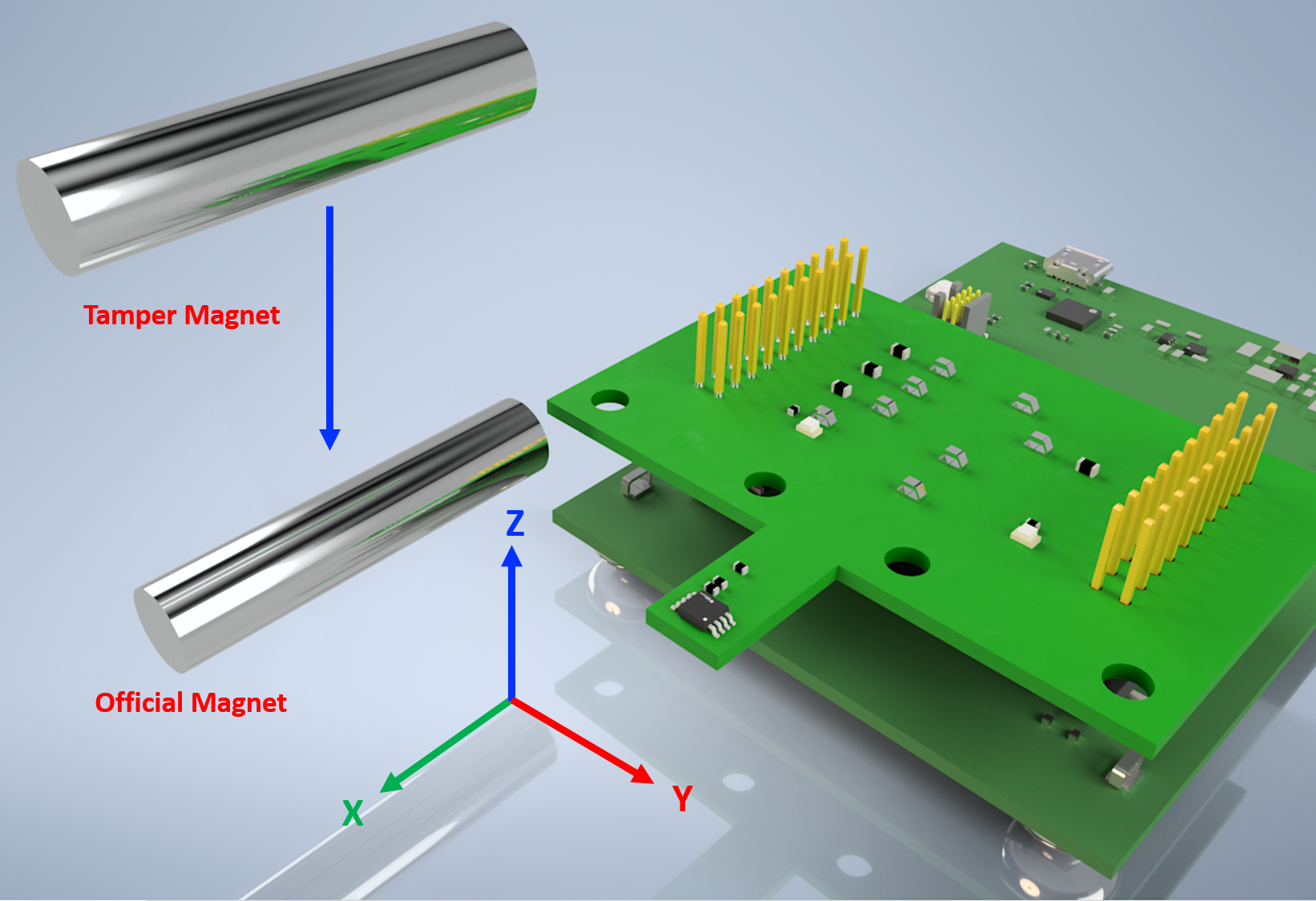
The tampering was done both orthogonally as well as parallel. Figure 7-7 shows the output from the TMAG5170 GUI when the fraudulent magnet is brought within the detection field of the device. The field strength is approximately 1.75mT on the X-axis until the imposter magnet is brought closer. The introduction of the second magnet increases the field strength on both the X as well as the Y axis, indicating a tamper attempt has occurred.
 Figure 7-7 TMAG5170 Orthogonal Tamper Testing
Setup
 Figure 7-8 TMAG5170 Orthogonal-Axis Magnetic Detection:
Results
Figure 7-8 TMAG5170 Orthogonal-Axis Magnetic Detection:
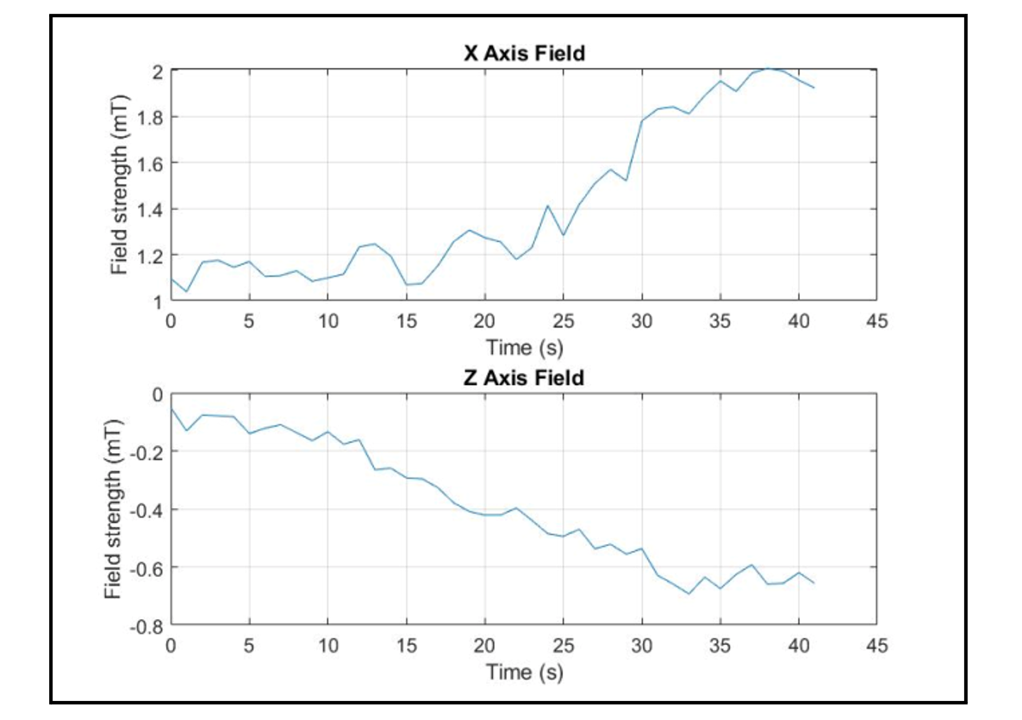
ResultsAgain, the tampering test is done, this time parallel to the genuine magnet. Figure 7-9 shows the resulting response from the TMAG5170 when the tamper magnet is brought within detection range. Before the tamper magnet begins the approach, the X axis field strength is approximately 1.1mT. Once the tamper magnet is brought closer, the evidence of tampering attempt can be seen on the Z axis with the field strength again increasing on the X axis due to the additional magnetic field presence.
 Figure 7-9 TMAG5170 Parallel Tamper Test: Setup
 Figure 7-10 TMAG5170 Parallel Tamper Test: Results