SBAA519A June 2021 – May 2024 DRV5055 , DRV5056 , TMAG5170 , TMAG5170-Q1 , TMAG5173-Q1 , TMAG5273 , TMAG5328
1
Many systems have moving components that must have the linear position calculated. Traditionally, mechanical-based designs, such as those using potentiometers, are used to measure linear position; however, due to the wear and tear associated with mechanical designs, many systems are moving towards a contactless method for linear position sensing.
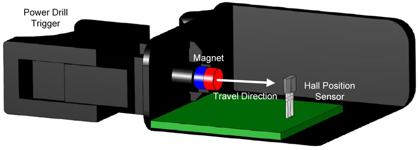
A robust contactless method for measuring linear position can be implemented using a magnet and a linear Hall position sensor that are arranged in a head-on configuration, as shown in Figure 1. In this approach, a magnet is placed on the moving component so that the magnet moves along with the component. The linear Hall position sensor senses the resulting magnetic flux density from the magnet.
An example moving component that requires linear position measurement is the variable speed trigger in power tools or other appliances, which measures how far the trigger is pressed and translates it into the operating speed of the tool. Figure 1 specifically shows an example of the placement of a cylinder magnet and Hall position sensor for a cordless power drill that uses a head-on configuration for translating how far the trigger is pressed into the speed of the drill. For this example, the magnet is closest to the Hall position sensor when the trigger is fully pressed and it is furthest when the trigger is unpressed. Using a similar approach to Figure 1, the head-on configuration can also be used for level or pressure sensing in washers and dryers and object or wall detection in a robotic vacuum.
 Figure 1 Head-on Configuration in a Power Drill Trigger
For the head-on configuration, the linear axis of measurement of the Hall position sensor is along the path of travel, which results in a unique mapping of distance to magnetic flux density if the magnet is inline with the sensing axis of the Hall position sensor.
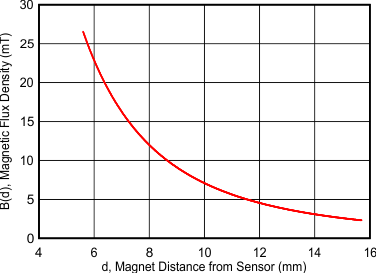
Figure 2 shows an example magnetic flux density versus distance graph, where the distance is the distance from the magnet to the Hall position sensor. The mapping of magnetic flux density to distance depends on various factors, such as the material and dimensions of the magnet. Generally, larger magnets and greater sensing distances can enable better positional accuracy than very small magnets at close distances because magnetic flux density increases exponentially with the proximity to a magnet. The DRV5056 Distance Measurement Tool calculates the expected magnetic flux density to distance mapping in a head-on configuration for different magnet specifications.
Based on the expected magnetic flux density to distance mapping, the system can translate the sensed magnetic flux density from the linear Hall position sensor into magnet displacement distance. Since the magnet moves with the moving component of the system, this magnet displacement distance also is the same as the linear position displacement of the moving component.
 Figure 2 Example Magnetic Flux Density vs Distance Graph
Selecting the Right Part for Head-on Displacement
A linear Hall position sensor must be used to detect the distance at multiple points along the travel path of the magnet. The appropriate Hall position sensor is often selected based on the following specifications:
- Sensitivity: Select a linear Hall position sensor so that the magnetic range is larger than the maximum magnetic flux density in the system while also making sure the maximum resolution is obtained for better accuracy. As an example, suppose that a Hall position sensor has sensitivity variants that result in a magnetic range of 20mT, 39mT, 79mT, and 158mT. If the maximum magnetic flux density that has to be sensed by the system is 45mT, select the sensitivity variant that corresponds to a 79mT range. The 79mT range enables sensing of the maximum magnetic flux density produced, which cannot be done by the 20 and 39mT variants. In addition, the 79mT variant has a better magnetic flux density resolution compared to the 158mT range option.
- Unipolar versus Bipolar: Bipolar Hall position sensors detect both the north and south poles of a magnet while unipolar only detects one. Head-on displacement configurations have a magnetic flux density that is either entirely positive or entirely negative, depending on whether the south or north pole of the magnet is closest to the sensor. As a result, a unipolar Hall position sensor can be used for head-on displacement configurations. Since unipolar sensors only sense one polarity, these sensors can have more sensing resolution compared to the corresponding bipolar device; however, since bipolar devices work with both poles of a magnet, this allows the magnet to be placed without determining whether a pole of the magnet is the south or north pole.
- Output Interface: Linear Hall position sensors can have an analog output voltage, a digital PWM output, or a digital communication interface like SPI or I2C. An analog output voltage is common for one-dimensional (1D) linear Hall position sensors and require an external ADC, which further adds to the error of the system. Digital communication interfaces are common for three-dimensional (3D) Hall position sensors that have an internal ADC that digitizes the sensed magnetic flux density into an output code that is read from the interface. For PWM output devices, the duty cycle ratio of the output pulse varies based on the sensed magnetic flux density. A PWM output provides more immunity to external noise.
- Operating Voltage Range: Different systems have different available supply voltages. If the available supply voltages of a system are all outside of the operating voltage range of the Hall position sensor, an additional voltage regulator device is needed to generate a voltage rail for powering the Hall position sensor.
- Frequency Bandwidth: When sampling a signal, the maximum bandwidth of the device must be greater than the frequency of the signal being sampled. Some devices like the DRV5056 define the bandwidth as the –3dB cutoff frequency. At this point, the sensitivity of the signal path is reduced by –3dB.
- Offset and Sensitivity Error: The offset error is the magnetic flux density reading when a magnetic field is not applied. The offset error can be expressed in terms of magnetic flux density, the resulting output voltage shift (for voltage outputs), the resulting pulse duty cycle shift (for PWM outputs), or the resulting change in output code (for digital communication interface outputs). The sensitivity is the factor that provides information on how the sensed magnetic flux density is translated by the device into either an output voltage, digital output code, or pulse duty cycle ratio. These two errors are taken at room temperature and can be calibrated out.
- Offset and Sensitivity Temperature Drift: The offset drift shows how the offset drifts across temperature. Similarly, the sensitivity drift shows how the sensitivity drifts across temperature. These two errors can be calibrated out by taking multiple calibration points across temperature and using a temperature sensor to determine the necessary correction points to use based on the measured temperature.
- Noise: To reduce the noise, multiple samples can be averaged to produce one effective sample. For an analog output device, a low-pass filter can also be used to reduce the noise if the full bandwidth of the device is not used. Note that both of these options reduce the frequency bandwidth of the device.
- Linearity Error: Measurement of how much the sensitivity transfer function deviates from a straight line.
- Current Consumption: To reduce current consumption in systems where linear position sensing is only required part of the time, the linear Hall position sensor can be powered down. Powering down is done by using the enable pin on the device (if available), removing power from the device, or by writing to the appropriate low power mode registers (if available).
- Ratiometric: For linear output Hall position sensors, a ratiometric architecture minimizes error from VCC tolerance when the external ADC uses the same VCC for reference.
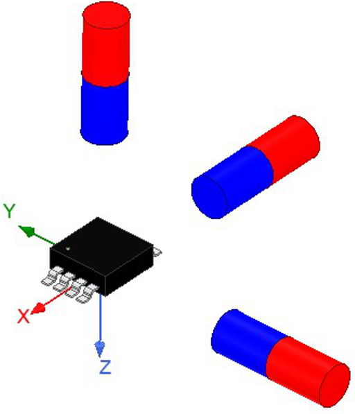
- In-plane versus Out-of-Plane Field Direction: In-plane 1D position sensors are sensitive to application of the magnet pole in the same plane as the die, similar to the application of the X- or Y-axis magnets shown in Figure 3. Out-of-plane 1D position sensors are sensitive to the magnetic field component that is perpendicular to the die inside the package. The Z-axis magnet in Figure 3 shows the out-of-plane orientation for a SOT23 surface mount package while Figure 1 shows the out-of-plane orientation for a TO-92 through-hole package. 3D Hall position sensors are sensitive to the magnetic field component in X, Y, and Z directions. The X and Y fields are in plane with the package while the Z field is perpendicular (out of plane) to the top of the package, as shown in Figure 3.
 Figure 3 X (In-Plane), Y (In-Plane), and Z (Out of Plane) Directions in an Example 3D Hall Position Sensor
The DRV5056 is offered in multiple versions, making this device and excellent choice for head-on displacement applications. The different sensitivity variants enable support for various distance and magnet combinations in linear position applications. This device is a unipolar device, which offers two times better resolution compared to the bipolar DRV5055. In addition, since the device is just a 3-pin analog output device, the device is smaller compared to 3D Hall position sensors that have I2C or SPI communication lines.
Since 3D linear position sensors can sense in all three directions, these sensors support measuring the linear position when the magnet moves in either the X, Y, or Z direction. Also, the sensors can better measure the linear position of a moving component when the magnet is offset with respect to the Hall position sensor axis. In addition to the different set of magnetic ranges obtained with different device variants, some 3D linear Hall position sensors such as TMAG5170, TMAG5273, and TMAG5173-Q1 also have an additional subset of magnetic ranges that can be selected from by configuring the appropriate device registers through the digital communication interface of the device (SPI for the TMAG5170 and I2C for the TMAG5273 and TMAG5173-Q1). The TMAG5170, TMAG5273, and TMAG5173-Q1 also have the option of internally averaging samples to reduce noise. In addition, these devices support sleep modes that can be used to reduce the current consumption of the device. Since the TMAG5170, TMAG5273, and TMAG5173-Q1 also have an integrated ADC, the device does not require an external ADC like the DRV5056.
Alternate Device Recommendations
The DRV5053 can also be used in applications that have a high supply voltage since the DRV5053 can support an input voltage up to 38V. For head-on displacement systems that ought to work even if the magnet has been installed in reverse, the DRV5055 omnipolar linear position sensor is also another option. If a PWM output is needed instead of an analog output, the DRV5057 is also another option. Table 1 has links that provide more details on the specifications of these alternate devices: