-
Improve System Performance With Linear 3D Hall-Effect Position Sensors SBAA530 September 2021 TMAG5170 , TMAG5170-Q1 , TMAG5173-Q1
-
Improve System Performance With Linear 3D Hall-Effect Position Sensors
Improve System Performance With Linear 3D Hall-Effect Position Sensors
Trademarks
All trademarks are the property of their respective owners.
1 Achieving High Accuracy at High Speeds
Achieving the highest accuracy possible often requires running a system at a lower speed, which decreases system performance. For applications requiring fast, real-time control – highly accurate measurements at high speeds – decreased system performance is not an option. One application with these requirements is a motor transport system, also known as a linear mover. A linear mover consists of a smart track system with built-in microcontrollers (MCUs) that enable independent positioning of each mover. This system configuration provides multiple advantages in automation control, including high transfer speeds, accurate positioning and the ability to move products forward and backward on the line to increase manufacturing efficiency.
Linear movers use an array of sensors to track the absolute position of a magnet mounted on the mover. As Figure 1-1 shows, the sensors are placed equidistant along the X-axis. Calculating the angle from the X and Z components of the magnetic fields using the adjacent linear 3D Hall-effect position sensors resolves the absolute position of the mover.

Figure 1-1 Conceptual Implementation of a Linear Mover Using Two Linear 3D Hall-Effect Position Sensors
For linear mover systems that require accuracy and high speeds, a high-performance linear 3D Hall-effect position sensor can reduce errors. Internally, these error sources occur because of sensitivity, offset, linearity, noise produced by temperature variations and input-referred magnetic noise that couples into each axis. Externally induced errors come from many sources: mechanical vibration, unintentional spatial variations and tolerances between the magnet and the sensor, fast-changing magnetic fields, and off-axis angle measurements.
An important aspect of a high-performance linear 3D Hall-effect position sensor is an onboard angle coordinate rotation digital computer (CORDIC) calculator that performs iterative trigonometric approximations in a two-dimensional space to calculate both angle and magnitude, achieving a resolution of 0.25 degrees. Performing this calculation on the device eliminates the need to post-process the magnetic information.
Fast-changing magnetic fields are problematic for linear 3D Hall-effect position sensors that do not have independent internal signal paths, which include single-axis measurement, gain adjustment, filtering, and data conversion. To reduce errors, 3D Hall-effect position sensors with a single data converter and a feature called pseudo-simultaneous sampling provide the best solution.
Figure 1-2 illustrates the ideal circumstance where sampling of Z and X1’ occurs at the same instance in time. With changing magnetic fields and a single signal path for taking measurements; however, this is not possible. With pseudo-simultaneous sampling, an average of the X component just before and just after X1‘ (labeled X1 and X2, respectively) is used as the X-axis value that matches up to Z. Assuming that changes in the B-fields are relatively linear over small intervals, the results are similar to the sampling of both axes at the same time.

Figure 1-2 XZX Pattern Example of Pseudo-Simultaneous Sampling
Linear 3D Hall-effect position sensors typically house sensor technologies that enable the sensing of magnetic fields both in-plane and perpendicular to the package. Because these are two distinct sensors, the magnetic noise for each is different. Therefore, it is advantageous to equalize the noise floor by averaging samples of each axis. A linear 3D Hall-effect position sensor that can average as many as 32 samples reduces the noise floor substantially.
A high-accuracy 3D Hall-effect position sensor that can take precise measurements at high speeds – such as the TMAG5170 – is very useful for this application. The TMAG5170 delivers ultra-high accuracy thanks to a maximum full-scale sensitivity error of ±2.6%, low sensitivity mismatch error (per axis), and low drift overtemperature. Such precision could eliminate the need for system-level calibration, which decreases total system cost. Additionally, the TMAG5170 delivers sample rates as high as 20 kSPS, which is fast enough for many linear mover applications. For more information on the impact of sample rate, see the Angle Measurement with Multi-Axis Hall-Effect Sensors application report.
2 Optimizing Power Consumption
Ensuring sufficient measurement accuracy and speed while consuming as little power as possible is also important for systems that monitor movement or position. This is essential for battery-powered or low-power systems, where the power consumption of the magnetic sensor could use a significant portion of a system’s total power. One example of this is a remote monitor for a factory floor that communicates with a programmable logic controller through a 4- to 20-mA loop.
Other battery- or low-powered application examples are door and window sensors used in building or home security systems. A door sensor with angle detection can detect an open-and-close event and measure how far the door has opened. It is possible to implement this capability with a ring magnet and a linear 3D Hall-effect position sensor embedded in a traditional door hinge (see Figure 2-1). For low-power applications, linear 3D Hall-effect position sensors should be placed in a low-power duty-cycle mode running at low frequencies of 5 Hz or less.

Figure 2-1 Example of Angle Detection in a Traditional Door-Hinge Application
An added benefit to using a linear 3D Hall-effect position sensor in this application is that only two axes of sensitivity monitor the angle, enabling the use of the third axis for detecting malicious magnetic tampering or disabling, such as placing a magnet over the sensor to trick the system into believing that the door is still closed.
The TMAG5170 offers various power options (see Table 2-1) to optimize system power consumption. Depending on application needs, the sensor can be set to full active conversion, standby, duty cycle, sleep or deep sleep.
| Power Modes | Operation |
|---|---|
| Active conversation | Produces a continuous stream of data. Used when fully analyzing or processing magnetic fields. Typical current consumption is in the low, single-digit mA range. |
| Standby | Device is in a low-power state and will start a measurement upon a prompt by the MCU. Current consumption is < 1 mA. |
| Duty cycle | The device is placed in a sleep mode and wakes up at specified intervals to take measurements. Current consumption is 1.3 µA at 1 Hz. |
| Sleep | Similar to duty-cycle mode, except that the device is waiting for an MCU prompt to take a measurement, rather than doing so on its own. |
| Deep sleep | The device is essentially powered down, consuming 5 nA of current. |
3 Achieving Greater Flexibility
The single most important design consideration when designing with a Hall-effect sensor is the placement of the sensor in relation to the magnet. Sensor placement inflexibility can lead to an undesirable end-product form factor. Because various mechanical aspects of new designs are often not well-defined early on in the design process, linear 3D Hall-effect position sensors must have configurable features, such as selectable magnetic sensitivity ranges, gain and offset correction, variable update rates, and temperature compensation. The TMAG5170 offers this capability. The versatility of this device enables configuration during any phase of design and is suitable for many applications.
In general, the remanence of a magnet, which is an indication of the magnetic flux density, decreases as the temperature increases. To improve system performance with different types of magnets (such as neodymium iron boron or ferrite magnets), a linear 3D Hall-effect position sensor with temperature compensation offers further flexibility. The TMAG5170 has onboard configurable temperature compensation and can also turn off if only the magnet or only the sensor are exposed to temperature changes.
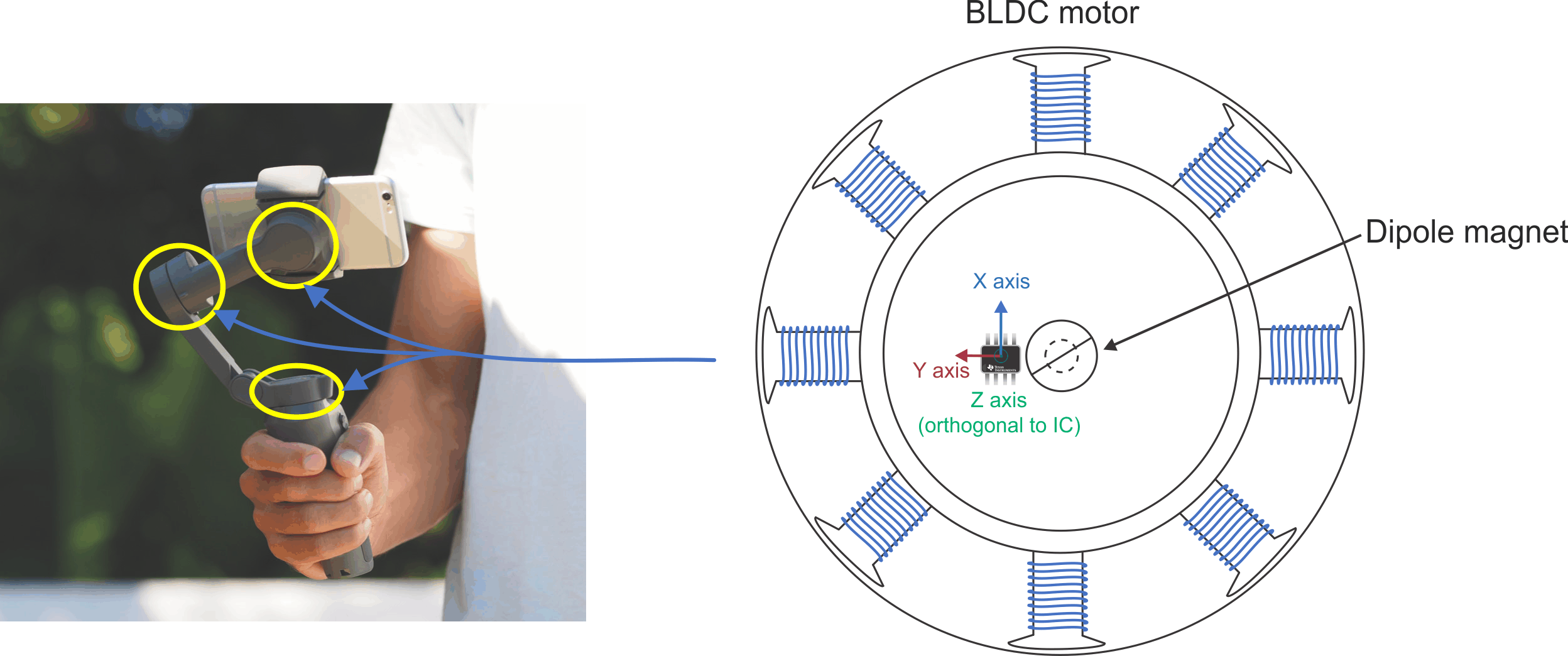
Gimbal motors are an example of an application that needs the flexibility of configurability to specific sensitivity ranges or other parameters. Gimbal motors are found in handheld camera stabilizers and drones to provide angle measurement information to the MCU. These motors stabilize footage by continuously adjusting the motor position as movement occurs. A sensor that can measure angles precisely and accurately while offering on- or off-axis placements (see Figure 3-1) enables mechanical flexibility in the magnet-to-sensor placement.

Figure 3-1 Off-Axis Angle Measurement Using 3D Linear in a Handheld Gimbal Motor
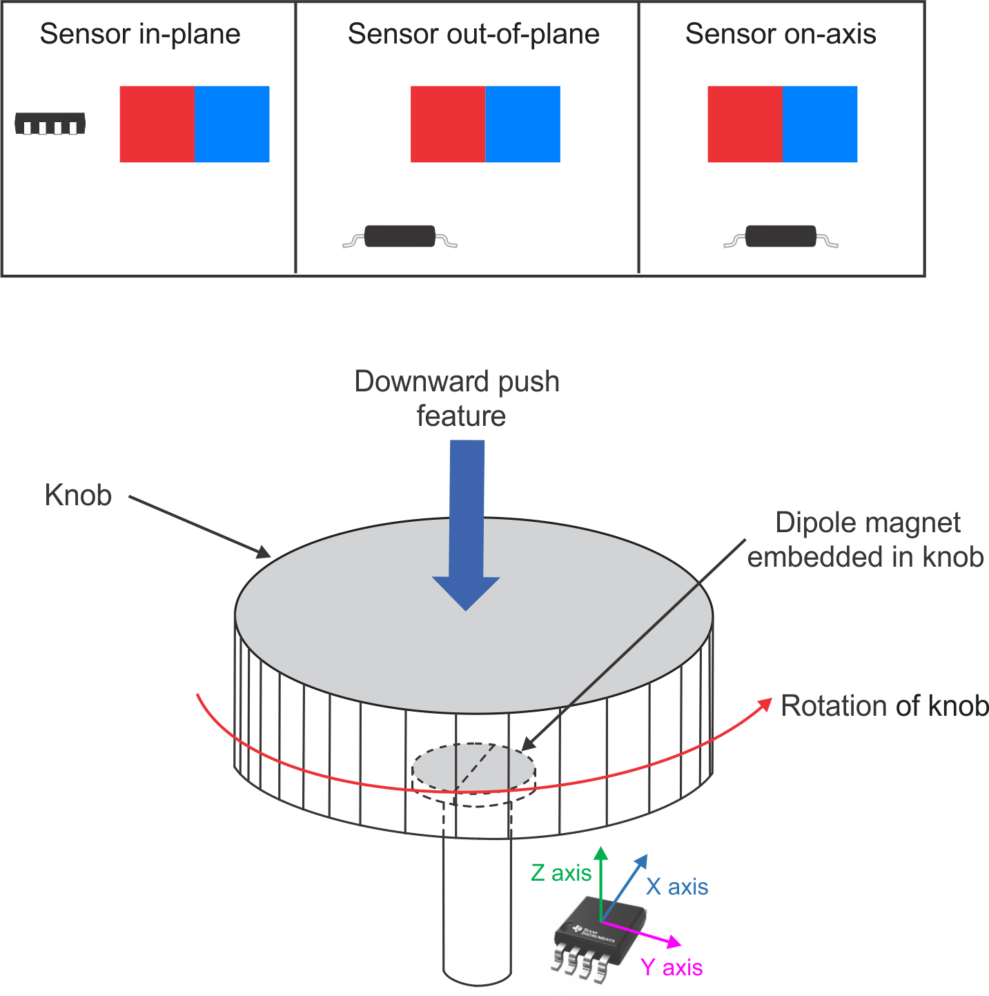
Human interface and controls in home appliances, test and measurement equipment, and personal electronics (see Figure 3-2) benefit from the capability of a linear 3D Hall-effect position sensor to precisely measure magnetic fields as the dial is turned. The magnetic field information is used to calculate the angle position between any two dimensions (XY, YZ, or ZX). As shown, the sensor out-of-plane configuration of the TMAG5170 implements the dial, but any of the three methods depicted in the figure can do so, enabling further flexibility. Aside from being able to implement a push feature by monitoring a large shift in the X and Y components, 3D sensitivity provides the ability to sense misalignment from the ideal configuration (by monitoring the third unused Z axis), providing alerts for predictive maintenance caused by wear and tear or damage to the dial.

Figure 3-2 Example Out-of-Plane Angle Measurement Using a Linear 3D Hall-Effect Position Sensor in a Knob or Dial Application
When calculating the angle measurements of rotating shafts, on-axis measurements (where the sensor is directly beneath or above the rotating magnet) provide the most accurate magnetic field measurements given the equivalent magnitude field vectors. In the case of the human interface and control knob shown in Figure 3-2; however, an on-axis implementation is not feasible because the shaft is obstructing the placement of the sensor. By monitoring the X and Y components, the magnetic fields are represented by sine and cosine functions, making it possible to calculate the angle between them using the arctangent function.
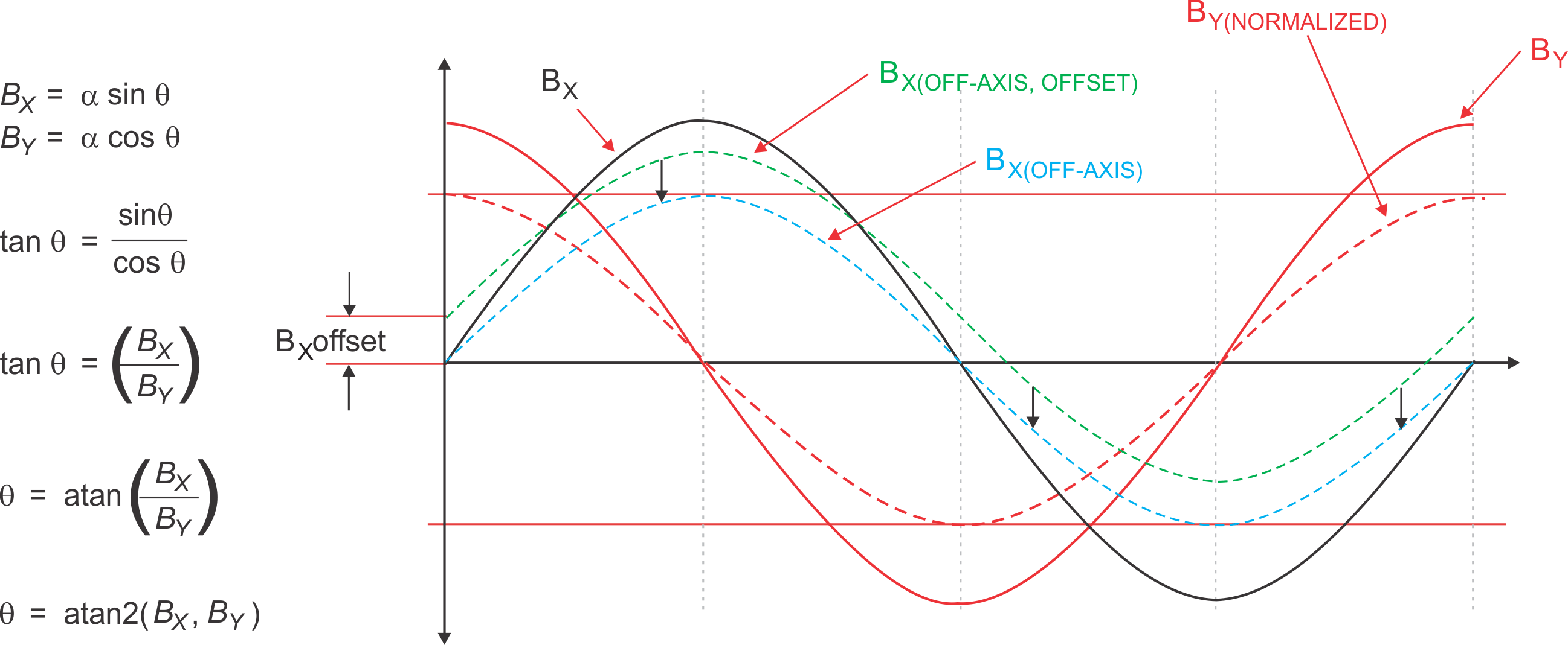
Figure 3-3 shows magnetic fields produced by a constant-speed rotating magnet, as in a dial. BX represents the magnetic field in the X direction, while BY is in the Y direction. These sine and cosine waveforms, BX and BY, are representative of an on-axis measurement. Out-of-plane implementations (previously shown in Figure 3-2) add complexity to the angle calculation given disparate magnetic field strengths. In this case, one magnetic field vector may be smaller in magnitude than the other – this is shown in the figure as BX(OFF-AXIS) in comparison to BX. Instead of having two well-behaved waveforms, the BX(OFF-AXIS) field is distorted, which produces an angle calculation error.
Yet another aspect of magnetic field measurement to consider is offset. Reducing the entire set of measurements by offset (shown by the three down arrows in Figure 3-3) and effectively producing field vectors for BX(OFF-AXIS, OFFSET) that match that of BX(OFF-AXIS) will compensate for the small magnetic field offset and ensure accurate rotation-angle calculation. For simplicity, only one axis of measurement has this offset; in reality, all axes will have an inherent offset that needs compensating. With the offset removed, one of the field vectors must be normalized to match the other. In this example, normalizing BY (shown as BY(NORMALIZED)) to match BX(OFF-AXIS) reduces it to a magnitude equal to BX(OFF-AXIS) divided by BY. Configuring the TMAG5170 with this gain and offset correction ensures the most accurate angle calculations, while also providing the flexibility to be placed where it is most convenient for the design.

Figure 3-3 XY Example for Gain-and-Offset Correction