SBAA591 December 2023 REF54
4.1 REF54250CDR Noise Measurement Setup
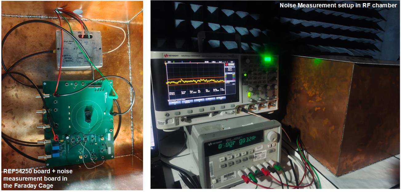
The output of REF54250CDR is connected to the filter board and both are kept in a Faraday cage inside RF chamber as shown in figure Figure 4-6. RF chamber cancels the echo, which avoids the coupling of any surrounding disturbance. Low PSRR power supply E3631 is used to power up the REF54250CDR and the noise board. Noise measurement has been done with a 100 μF capacitor connected on the NR pin and no capacitor connected to the NR pin. Time domain plot is captured on the scope with sampling frequency = 100 k samples a second (>>20 samples a second) for 10 seconds to capture the impact of 0.1 Hz to 10 Hz on peak to peak noise
An oscilloscope is used to analyze the time domain plot with high density. If the user wants to measure peak to peak noise, then 8.5 digit DMM is a better alternate as DMM has better ADC resolution and has options for differential probing to avoid any possibility of scope ground noise injection. Users can record the value with 100 samples a second for a period of 10 seconds and get peak to peak variation.
 Figure 4-3 REF54250 Noise Measurement
Setup
Figure 4-3 REF54250 Noise Measurement
SetupFigure 4-4 shows a typical measurement plot of REF54250CDR with a 100 μF capacitor on NR pin.
 Figure 4-4 REF54250 Noise Plot With 100
μF Capacitor on NR Pin
Figure 4-4 REF54250 Noise Plot With 100
μF Capacitor on NR PinTypical flicker noise for REF54250CDR with 100 μF NR pin capacitor is measured as 275 nV pk-pk (0.11 ppmpp ). 40 nV pk-pk noise from the filter board contributes 1.5% error in the noise measurement. REF54250CDR has 1.125 μV pk-pk (0.45 ppm pk-pk) flicker noise with open NR pin condition, which has less than 0.1% error from setup noise.
 Figure 4-5 0.1-Hz to 10-Hz Voltage
Noise (CNR = Open )
 Figure 4-6 0.1-Hz to 10-Hz Voltage
Noise (CNR = 100 μF)