SBAU126E may   2007  – june 2023 ADS1158 , ADS1258


  1.   1
  2.   Abstract
  3.   Trademarks
  4. 1ADS1258EVM Overview
    1. 1.1 ADS1258EVM Kit
    2. 1.2 ADS1258EVM
  5. 2Getting Started With the ADS1258EVM
  6. 3Analog Interface
    1. 3.1 Analog Input Options
    2. 3.2 ADC Connections and Decoupling
    3. 3.3 Configurable Multiplexer Loop
      1. 3.3.1 Measuring Single-Ended Inputs Using a Pseudo-Differential Configuration
    4. 3.4 Clocking
    5. 3.5 Voltage Reference
  7. 4Digital Interface
    1. 4.1 GPIO
  8. 5Power Supplies
  9. 6Software Installation
  10. 7EVM Operation and GUI
    1. 7.1 Connecting the Hardware
    2. 7.2 EVM GUI Global Settings for ADC Control
    3. 7.3 Time-Domain Display
    4. 7.4 Frequency-Domain Display
    5. 7.5 Histogram Display
  11. 8Bill of Materials, Layout, and Schematics
    1. 8.1 Bill of Materials
    2. 8.2 EVM PCB Layout
    3. 8.3 Schematics
  12. 9Revision History

EVM GUI Global Settings for ADC Control

Figure 7-3 shows that the EVM global controls are located on the left side of the GUI. These controls include the sampling mode, data rate, MUXOUT connection, switch time delay, channel selection, number of samples, and others. The Pages control in the upper-left corner allows access to the other pages in the GUI. Figure 7-3 also shows the available ADC register settings. The registers can be used to configure the ADC data rate, channel sequencer, or integrated features. Change the register settings by clicking on each bit, typing a value directly into the Value column, or by selecting from the drop-down menus in the Field View control.
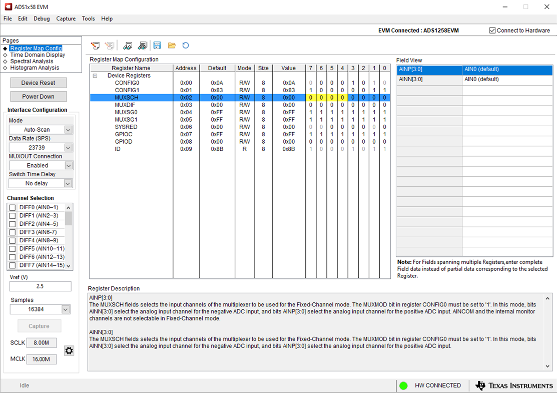
GUID-20221026-SS0I-BJF0-0NXT-5RT011TZXZKD-low.png Figure 7-3 ADS1258EVM GUI Global Settings for ADC Control Page