SBAU376A December 2021 – March 2022 TMAG5328
- 1
- Abstract
- Trademarks
- 1Overview
- 2Kit Contents
- 3Related Documentation From Texas Instruments
- 4Hardware
- 5EVM Operation
- 6Schematics, PCB Layout, and Bill of Materials
- 7Revision History
5.3 Head-On Linear Displacement Demo
The TMAG5328EVM kit comes with a 3D-printed head-on linear displacement module with an embedded magnet. When connected to the TMAG5328EVM, the module creates a magnetic field that is sensed by the TMAG5328. The module has two portions: a screw and a base. The base is connected to the EVM and the screw is placed inside the base. A magnet is embedded within the screw, which produces the magnetic field sensed by the TMAG5328. Figure 5-22 shows an exploded view of the different components within the module.
 Figure 5-22 Exploded View
of the Head-On Linear Displacement Attachment.
 When the screw is rotated clockwise inside the base, the magnet gets closer to the TMAG5328, thereby increasing the sensed magnetic flux density. If the screw is turned counterclockwise within the base, the screw increases its distance with respect to the TMAG5328, which decreases the sensed magnetic flux density.
To use this module with the TMAG5328EVM, perform the following steps:
- Connect the base of the module to the TMAG5328EVM
(see Figure 5-23).
 Figure 5-23 Base Connected to TMAG5328EVM.
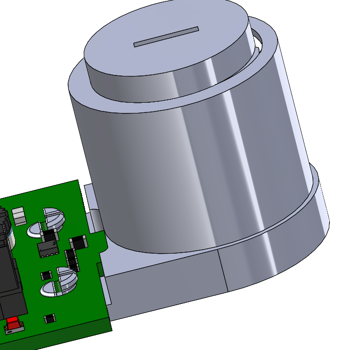
 - Place the screw at the top of the base (see Figure 5-24).
As the screw is brought near the top of the base, the sensed
magnetic flux density will approach around 2 mT.
 Figure 5-24 Screw Placed at Top of Base.
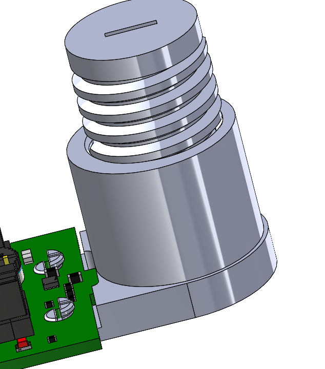
 - When the screw is at the top of the base, turn
the screw clockwise to bring screw and its embedded magnet
closer to the TMAG5328. After the screw is turned clockwise,
the TMAG5328 OUT pin will be asserted low when the sensed
magnetic flux density becomes greater than the set
BOP. After the screw is fully secured
into the base (see Figure 5-25),
the sensed magnetic flux density will be larger than the
15-mT BOP maximum that is supported by the
TMAG5328, so the TMAG5328 OUT pin will be asserted low and
LED D1 will be ON.
 Figure 5-25 Screw Fully Fastened Into Base.
For more information on the Head-On Linear Displacement attachment, refer to the Head-on Linear Displacement 3D Attachment user's guide.