SBAU377 September 2021
4.1 8x Complex Decimation
This example uses a coherent 790 MHz input on the channel A input with the ADC in a 1x averaging mode with dither enabled.
Procedure
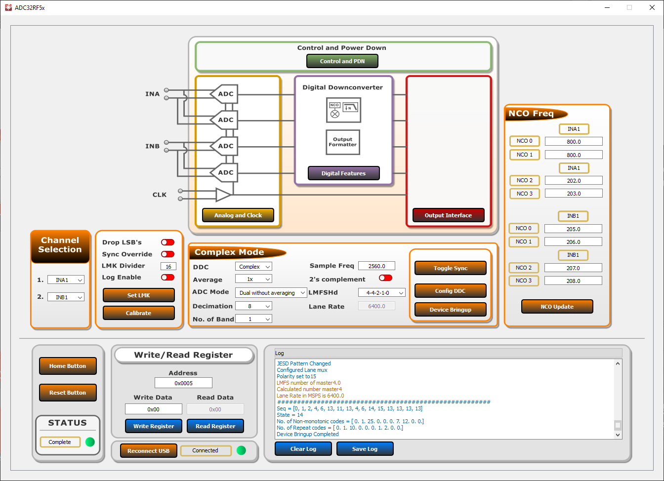
- In the Bypass Mode box, use the DDC dropdown to change to Complex Mode. The usser will notice the box title changes to Complex Mode to reflect the current DDC operating mode.
- Use the Decimation dropdown to change the decimation to 8.
- Set the LMFSHd setting to 4-4-2-1-0.
- Set the channel INA1 NCO0 and NCO1 to 800 (MHz).
- Change LMK divider from 8 to 16.
- Once these settings are verified
and match Figure 4-1, press the
Device Bringup button.
 Figure 4-1 ADC32RF5xEVM GUI, 8x
complex decimation, 800 MHz NCO
 - Wait until after the message Device Bringup Completed appears in the Log.
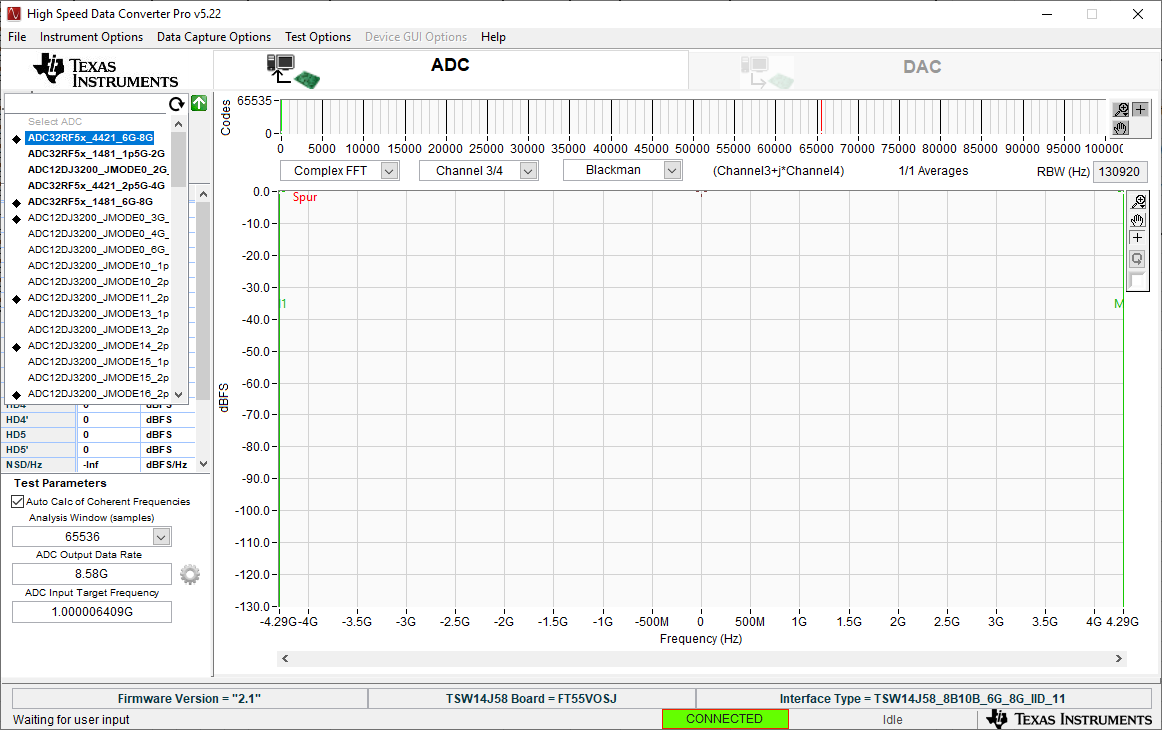
- In HSDC Pro, connect to the
TSW14J58EVM and select ADC32RF5x_4421_6G-8G as the INI file shown in
Figure 4-2.
 Figure 4-2 ADC32RF5x_4421_6G-8G
INI file
 - Update the firmware by pressing Yes on the pop-up window and waiting for the Downloading Firmware message to finish.
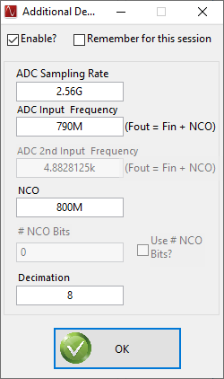
- Open the Additional Device Parameters menu by clicking on the gear next to the ADC Output Data Rate field.
- Check the tickbox labeled
"Enable?" and then enter the parameters shown in Figure 4-3.
 Figure 4-3 Additional Device
Parameters , 8x complex decimation
 - Once completed, press OK.
- Check the tickbox labeled Auto Calculation of Coherent Frequencies and you will see the ADC Input Target Frequency change from 790 M to the coherent frequency. Set the signal generator connected to channel A input to this coherent frequency.
- Change the view window from Real FFT to Complex FFT and select channel 1/4.
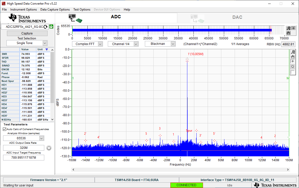
- Press the Capture button. You should now see something similar to Figure 4-4.
- Adjust signal generator output such that the measured fundamental power in HSDC Pro is at the user's desired level.
 Figure 4-4 789.995 MHz input, 8x complex
decimation, 1x averaging, dither on