SBAU394A April 2022 – September 2022
- ADS1285 Evaluation Module
- Trademarks
- 1 EVM Overview
- 2 ADS1285EVM-PDK Quick-Start Guide
- 3 EVM Analog Interface
- 4 Digital Interface
- 5 Power Supplies
- 6 Digital-to-Analog Converter
- 7 ADS1285EVM-PDK Initial Setup
- 8 ADS1285EVM-PDK Software Reference
- 9 ADS1285EVM-PDK Bill of Materials, PCB Layout, and Schematics
- 10References
- 11Revision History
7.1 Default Jumper Settings
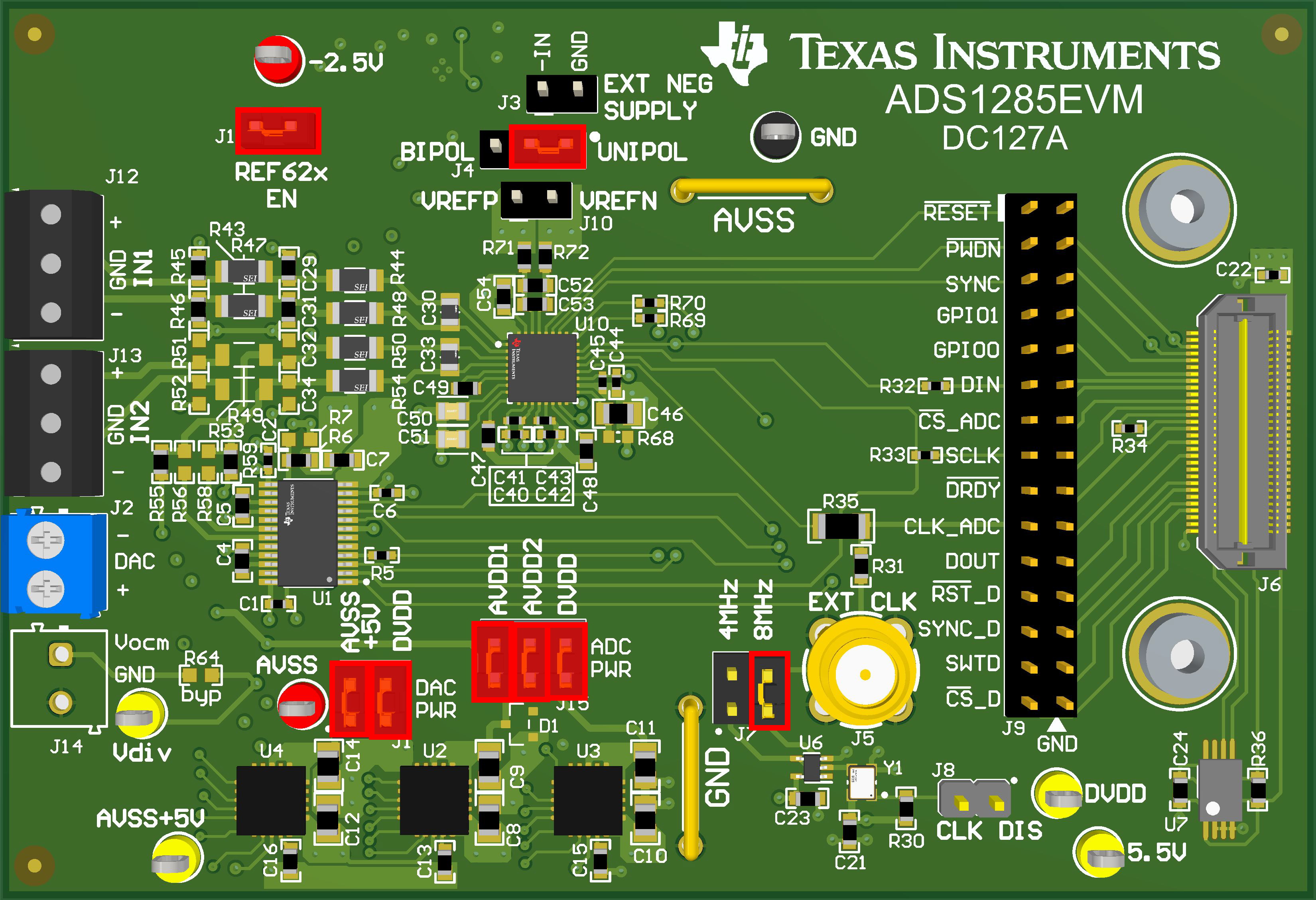
After unpacking, the EVM is already configured with the default jumper settings. Figure 7-1 shows the locations for the default jumpers and Table 7-1 shows the functions of the default shunts.
 Figure 7-1 ADS1285EVM-PDK Jumper Default Settings
Table 7-1 Default Shunt Settings
| Header Designator | Position | Function |
|---|---|---|
| J11 | [1-2] | Enables the REF62x supply to VREFP |
| J4 | [1-2] | Connects AVSS to GND for unipolar ADC supply mode |
| J7 | [3-4] | Connects CLK to an 8.192-MHz source from the crystal oscillator |
| J10 | Not installed | Header to supply the external reference voltage to VREFN and VREFP |
| J1 | [1-2] | DAC PWR: Connects the output of the U4 LDO (AVSS+5V) to the DAC analog supply pin (AVDD) |
| J1 | [3-4] | DAC PWR: Connects the PHI digital supply (DVDD) to the DAC digital supply pin (DVDD) |
| J15 | [1-2] | ADC PWR: Connects the output of the U2 LDO (AVDD1) to the ADC analog supply 1 (AVDD1) |
| J15 | [3-4] | ADC PWR: Connects the output of the U3 LDO (AVDD2) to the ADC analog supply 2 (AVDD2) |
| J15 | [5-6] | ADC PWR: Connects the PHI digital supply (DVDD) to the ADC digital supply (IOVDD) |
| J3 | Not installed | Header to supply the external input to U5 for the –2.5-V supply |
| J8 | Not Installed | Enables 8.192-MHz crystal oscillator |
Table 7-2 lists the nominal voltages that result from the default configuration.
Table 7-2 Nominal Voltages Resulting From a Default Configuration
| Supply Name | Voltage (Referenced to GND) |
|---|---|
| AVSS | GND (0 V) |
| AVSS+5V | 5 V |
| DVDD (IOVDD) | 3.3 V |
| AVDD1 | 5 V |
| AVDD2 | 5 V |
| 5.5V | 5.5 V |
| REFP | 4.096 V |
| –2.5V | NA, external supply needed to generate –2.5 V |