SBAU398 March 2022
2.2.3 External Microphone Configurations
The PCMx120-Q1 family of devices support both analog and digital PDM inputs with up to 2 channels of analog input or 4 channels of digital PDM input. It is also possible to use various combinations of analog and digital inputs with up to 2 analog inputs and 2 digital inputs operating simultaneously.
Single-ended or differential analog inputs can be applied on the following pin pairs: IN1P, IN1M, IN2P_GPI1, IN2M_GPO1.
Digital PDM inputs can be applied to the following pins: IN2P_GPI1, MICBIAS_GPI2, GPIO1. A PDM clock can also be output on pins: IN2M_GPO1, GPIO1.
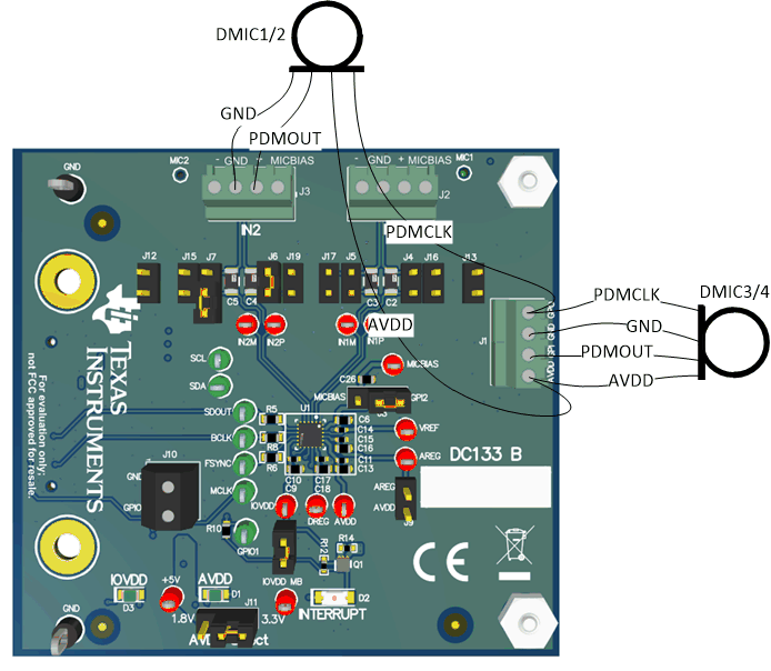
On the EVM access to these pins is provided on terminals J1, J2, J3, and J10. Figure 2-10, Figure 2-11, and Figure 2-12 illustrate the recommended pin connections for common use-cases.
Note, the GPIO1 pin is referenced to the IOVDD domain while IN2P_GPI1, MICBIAS_GPI2, and IN2M_GPO1 are all referenced to AVDD. Thus, if using 2 analog mics in addition to digital mics it is recommended that AVDD and IOVDD be set to the same voltage or a level translator be placed between GPIO1 and the digital microphone. If only 1 analog mic is used then it is recommended to use IN1P and IN1M for the analog mic. If digital mics are used, it is recommended to use IN2M_GPO1 to generate the PDMCLK signal.
 Figure 2-10 External Mics: 2x Analog Microphones
 Figure 2-11 External Mics: 4x Digital Microphones
 Figure 2-12 External Mics: 2x Analog and 2x Digital Microphones