SBAU398 March   2022


  1.   Trademarks
  2. 1Introduction
  3. 2Hardware Overview
    1. 2.1 AC-MB Settings
      1. 2.1.1 Audio Serial Interface Settings
        1. 2.1.1.1 USB
        2. 2.1.1.2 Optical or Auxilary Analog Audio Input
        3. 2.1.1.3 External
      2. 2.1.2 AC-MB Power Supply
    2. 2.2 ADCx120Q1EVM-PDK Hardware Settings
      1. 2.2.1 Line Inputs
      2. 2.2.2 Onboard Microphone Configuration
      3. 2.2.3 External Microphone Configurations
  4. 3Software Overview
    1. 3.1 PurePath Console 3 Installation
    2. 3.2 ADCx120Q1EVM GUI Installation
      1. 3.2.1 Software Setup
  5. 4GPIO1 Settings
  6. 5Master Mode Operation
  7. 6Quick Start
    1. 6.1 Configuring the Audio Serial Bus for the I2S Output
    2. 6.2 Saving a Configuration
  8. 7Schematic and Bill of Materials
    1. 7.1 ADCx120Q1EVM-PDK Schematic and Bill of Materials
      1. 7.1.1 ADCx120Q1EVM-PDK Schematic
      2. 7.1.2 ADCx120Q1EVM-PDK Bill of Materials
    2. 7.2 AC-MB Schematic and Bill of Materials
      1. 7.2.1 AC-MB Schematic
      2. 7.2.2 AC-MB Bill of Materials
    3. 7.3 Matlab Audio Capture Example

Software Setup

Open the PPC3 application in the directory chosen for the GUI installation in Section 3.1. Figure 3-2 shows the resulting app center window. Click on the PCMx120-Q1 app tile.

GUID-20220401-SS0I-ZVNN-RKTV-JK5STFTQDXHG-low.png Figure 3-2 PurePath Console 3 App Center

The PCMx120-Q1 GUI is designed to work with up to four devices at any time. As shown in Figure 3-3, choose the 1 device radial button and click New.

GUID-20220401-SS0I-WN9W-4KPZ-QGFVPVMRDHZM-low.png Figure 3-3 Initial GUI Configuration

As shown in Figure 3-4, the GUI opens to the Audio Config tab.
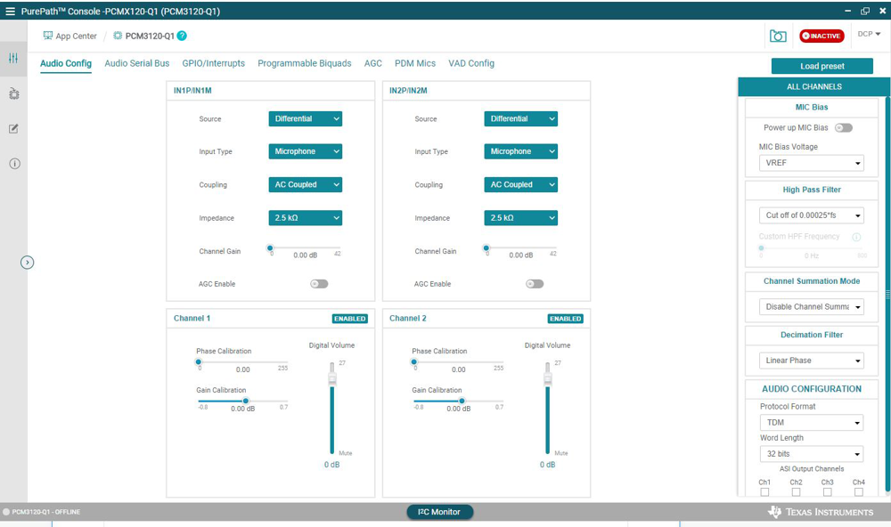
GUID-20220401-SS0I-2CHZ-XFPH-GTJXSR1G8PJH-low.png Figure 3-4 Audio Config Tab

Before changing any parameters, check the lower left corner of the PPC3 window, as shown in Figure 3-5, to verify that the EVM is connected. If no EVM is detected, the text will read PCMx120-Q1 offline. If the EVM is detected, a Connect button appears. Clicking this button connects the hardware.

GUID-20220401-SS0I-K09J-MWHW-DBKKX9SVDJXL-low.png Figure 3-5 Hardware Connect

When the hardware is connected, the Connect button changes to read Disconnect, and the device is ready to be configured.