SBAU400 November 2023 TMAG5253
4.3 PCB Layout
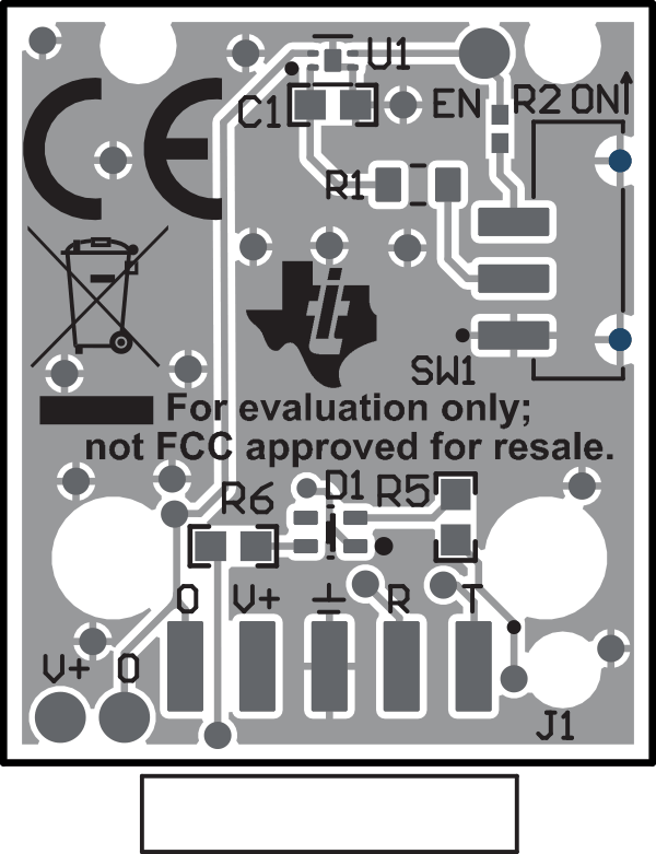
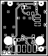
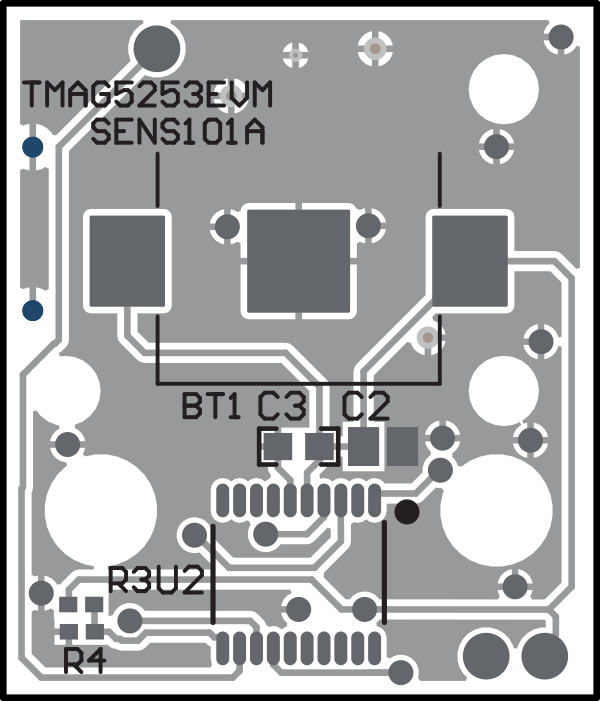
Figure 4-2 through Figure 4-5 show the PCB layers of the EVM.
 Figure 4-2 Top View
 Figure 4-4 Top Layer
 Figure 4-3 Bottom View
 Figure 4-5 Bottom Layer
SBAU400 November 2023 TMAG5253
Figure 4-2 through Figure 4-5 show the PCB layers of the EVM.
 Figure 4-2 Top View
 Figure 4-4 Top Layer
 Figure 4-3 Bottom View
 Figure 4-5 Bottom Layer