SBAU420 March 2023
3.2.2 Rotate and Push Demonstration
To use the rotate and push demonstration, follow these steps:
- Attach the Rotate & Push module to the EVM as shown in #ID-4951AE70-4DD3-48D6-FEDA-CF3B6266B67A. Figure 3-10 Rotate & Push Module on EVM
- In the GUI register page:
- At this time the Rotate & Push GUI will only show results for the device selected on the register map page.
- Make sure that the DEVICE_CONFIG → OPERATING_MODE says (TRIGGER_MODE Active).
- Make sure that SYSTEM_CONFIG → TRIGGER_MODE is set to the default value.
- Under the SENSOR_CONFIG register:
- Make sure both the X and Y channels are enabled (MAG_CH_EN).
- Set X_RANGE and Y_RANGE to ±100 mT for A1 versions, and ±133 mT for A2 versions.
- Optional: Set ANGLE_EN to X-Y angle calculation.
- At the top of the register map, set Auto Read to As fast as possible.
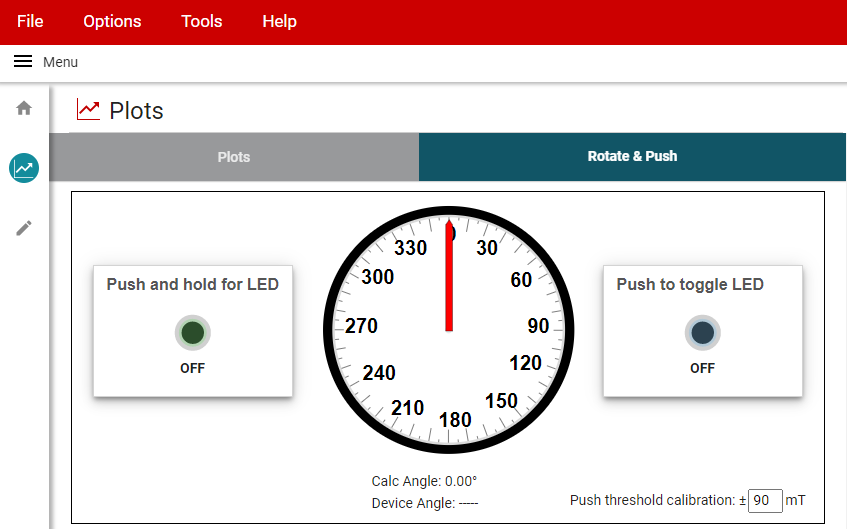
- Go to the Rotate & Push tab inside the Plots page (see #ID-06CECCE4-684B-41B0-80C1-4BC0FAAE0B58).
 Figure 3-11 Rotate & Push GUI Page
 - If the push button LEDs are not triggering at every angle or trigger when they are not supposed to, calibrate the module by doing the following:
- With the settings set to run the demo, slowly rotate the module 360° and use the Plots page to record the absolute value of the minimum and maximum magnetic field measurements (in mT) for both the X and Y channels.
- Adjust the Push threshold calibration value found in the Rotate & Push tab to be about 3 mT to 5 mT larger than the maximum value recorded above.