SBAU466 October 2024 DAC39RF10 , TRF1108
- 1
- Description
- Features
- Applications
- 5
- 1Evaluation Module Overview
-
2Hardware
- 2.1 Required Equipment
- 2.2
Setup Procedure
- 2.2.1 Installing the High Speed Data Converter (HSDC) Pro Software
- 2.2.2 Installing the DAC39RF10EVM Configuration GUI Software
- 2.2.3 Connect the TRF1108-DAC39RFEVM and TSW14J59EVM
- 2.2.4 Connect the Power Supplies to the Boards (Power Off)
- 2.2.5 Connect the Spectrum Analyzer to the EVM
- 2.2.6 Turn On the TSW14J59EVM Power and Connect to the PC
- 2.2.7 Turn On the TRF1108-DAC39RFEVM Power Supplies and Connect to the PC
- 2.2.8 Turn On the Signal Generator RF Outputs
- 2.2.9 Launch the DAC39RF10EVM GUI and Program the DAC EVM
- 2.2.10 Programming the NCO
- 2.2.11 Launch the HSDCpro Software and Load the FPGA Image to the TSW14J59EVM
- 2.3 Device Configuration
- 2.4 Troubleshooting the TRF1108-DAC39RFEVM
- 2.5 Customizing the EVM for Optional Clocking Support
- 2.6 Signal Routing
- 2.7 Jumpers and LEDs
- 3Hardware Design Files
- 4Additional Information
- 5References
2.2.11 Launch the HSDCpro Software and Load the FPGA Image to the TSW14J59EVM
- Launch the HSDCpro 5.303 or later software.
- Click OK to confirm the serial number of the TSW14J59EVM device. If multiple TSWxxxxx boards are connected, then select the model and serial number for the one connected to the TRF1108-DAC39RFEVM.
- For the Device, select DAC from the drop-down menu.Note: If the pop-up window says No Firmware, then select a device to load firmware into the board and click OK to proceed to the next step.
Figure 2-8 Launching HSDCpro and Setup
- Select the DAC39RF1x_JMODE0 device from the DAC select drop-down in the top left corner.
- When prompted, click Yes to update the
firmware (wait for firmware to download). Note: If the user configures the EVM with options other than the default register values, then different instructions can be required for selecting the device in HSDC Pro. For more details, see Section 2.5.
Figure 2-9 HSDCpro Setup
- Enter the data rate as 10.24G or the desired input data rate. The data rate value can be referenced from the DAC39RF10EVM GUI and is displayed on output parameter as shown in Figure 2-3.
- For DAC Option drop-down, select the Offset Bin option. The DAC39RF10EVM GUI always defaults to offset binary.
- Navigate to lower left side of the HSDCpro GUI to I/Q Multitone Generator section. For # of tones, enter 1. For Tone Center, enter 1G (1GHz or desired frequency); # of samples can be left 65536.
- Tone selection needs to be Real, since this is JMODE0; the DUC/ NCO is bypassed. If another JMODE was configured, such that DUC/NCO was used, then the Tone selection needs to be Complex.
- Click Create Tones button and then click Send in upper left side of HSDCpro GUI. If a pop-up window appears mentioning the SERDES RATE, then click OK. The DAC sends the programmed frequency to the outputs.
 Figure 2-10 HSDCpro Generating the Tone and Sending to the DAC
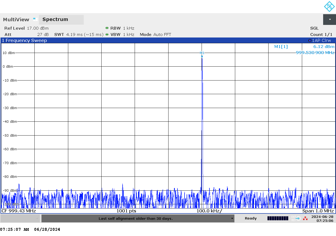
 Figure 2-11 DAC Output Displayed on Spectrum Analyzer