SBOA295A June 2018 – September 2024 INA138 , INA138-Q1 , INA139 , INA139-Q1 , INA168 , INA168-Q1 , INA169 , INA169-Q1
| Input | Output | Supply | |||||
|---|---|---|---|---|---|---|---|
| Iload Min | Iload Max | Vout Min | Vout Max | Vcm Min | Vcm Max | Vee | |
| 0.5A | 9.9A | 250mV | 4.95V | 12V | 400V | GND (0V) | |
Design Description
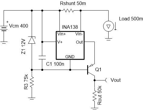
This cookbook is intended to demonstrate a method of designing an accurate current sensing option for systems with high common mode voltages. The principle aspect of this design uses a unidirectional circuit to monitor a system with Vcm = 400V by floating the supplies of the device across a Zener diode from the supply bus (Vcm). This cookbook is based on the High Voltage 12V – 400V DC Current Sense Reference Design.

Design Notes
- The Getting Started with Current Sense Amplifiers video series introduces implementation, error sources, and advanced topics for using current sense amplifiers.
- This example is for high VCM, high-side, unidirectional, DC sensing.
- To minimize error, make the shunt voltage as large as the design will allow. For the INA138 device, keep Vsense >> 15mV.
- The relative error due to input offset increases as shunt voltage decreases, so use a current sense amplifier with low offset voltage. A precision resistor for Rshunt is necessary because Rshunt is a major source of error.
- The INA138 is a current-output device, so voltages
referenced to ground are achieved with a high voltage bipolar junction
transistor (BJT).
- Verify that the transistor chosen for Q1 can withstand the maximum voltage across the collector and emitter (for example, need 400V, but select > 450V for margin).
- Multiple BJTs can be stacked and biased in series to achieve higher voltages
- High beta of this transistor reduces gain error from current that leaks out of the base
Design Steps
- Determine the operating load
current and calculate Rshunt:
- Recommended Vsense is 100mV and maximum
recommended is 500mV, so the following equation can be used to calculate
Rshunt where Vsense ≤ 500mV:

- For more accurate and precise measurements over the operating temperature range, a current monitor with integrated shunt resistor can be used in some systems.
- Recommended Vsense is 100mV and maximum
recommended is 500mV, so the following equation can be used to calculate
Rshunt where Vsense ≤ 500mV:
- Choose a Zener diode to create an
appropriate voltage drop for the INA138 supply:
- The Zener voltage of the diode falls in the INA138 supply voltage range of 2.7V to 36V and needs to be larger than the maximum output voltage required.
- The Zener diode voltage regulates the INA138 supply and protects from transients.
- Data sheet parameters are defined for 12V Vin+ to the GND pin so a 12V Zener is chosen.
- Determine the series resistance
with the Zener diode:
- This resistor (R3) is the main power consumer due to
its voltage drop (up to 388V in this case). If R3 is too low, it
dissipates more power, but if it is too high R3 does not allow the Zener
diode to avalanche properly. Since the data sheet specifies
IQ for VS = 5V, estimate the maximum quiescent
current of the INA138 device at VS = 12V to be 108µA and
calculate R3 using the bias current of the Zener diode, 5mA, as shown:

- The power consumption of this resistor is calculated
using the following equation:

- This resistor (R3) is the main power consumer due to
its voltage drop (up to 388V in this case). If R3 is too low, it
dissipates more power, but if it is too high R3 does not allow the Zener
diode to avalanche properly. Since the data sheet specifies
IQ for VS = 5V, estimate the maximum quiescent
current of the INA138 device at VS = 12V to be 108µA and
calculate R3 using the bias current of the Zener diode, 5mA, as shown:
- Calculate Rout using the equation for output current
in the INA138 data sheet.
- This system is designed for 10 V/V gain where
Vout = 1V if Vsense = 100mV:


- This system is designed for 10 V/V gain where
Vout = 1V if Vsense = 100mV:
Design Simulations
DC Simulation Results
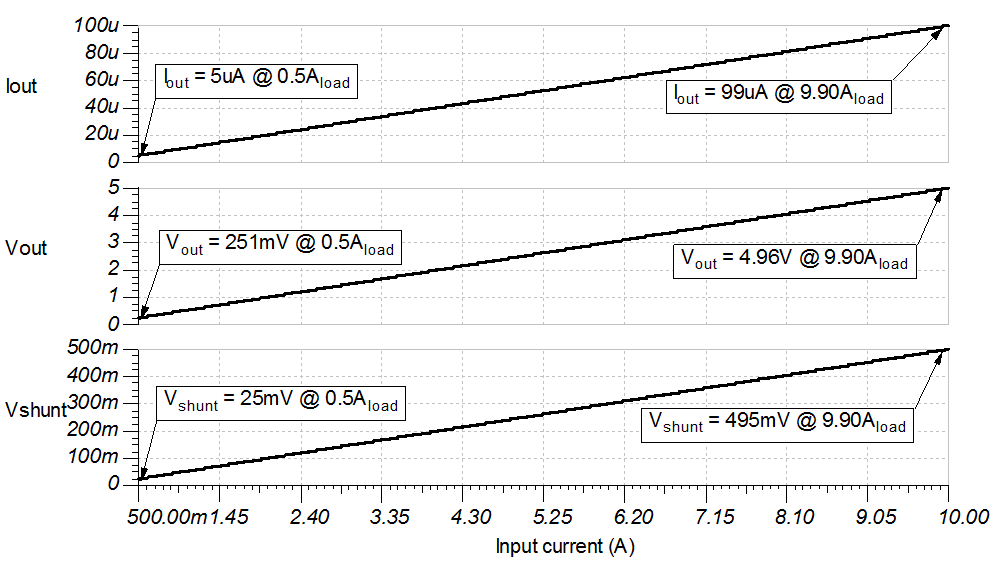
The following graph shows a linear output response for load currents from 0.5A to 10A and 12V ≤ Vcm ≤ 400V. Iout and Vout remain constant over a varying Vcm once the Zener diode is reverse biased.

Steady State Simulation Results
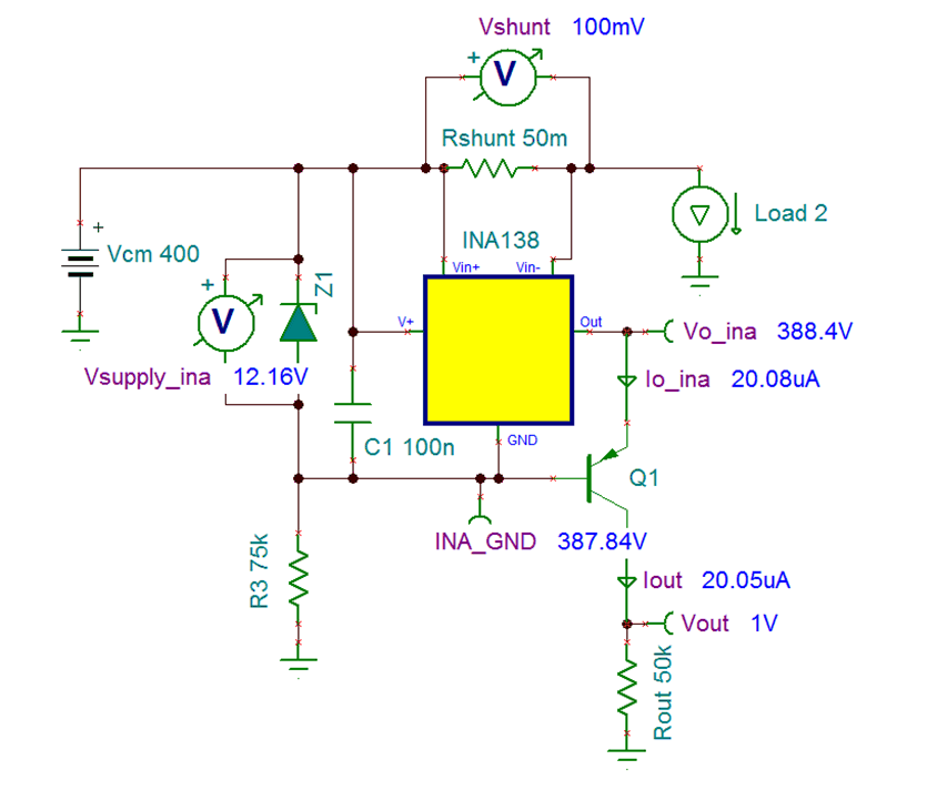
The following image shows this system in DC steady state with a 2A load current. The output voltage is 10× greater than the measured voltage across Rshunt.

Design References
Texas Instruments,SPICE SGLC001 simulation files, SBOA295 software support
Texas Instruments, Current sense amplifiers, Precision lab video series
Texas Instruments, Extending the Common-Mode Voltage Range of Current-Output Current Shunt Monitors, application brief
Texas Instruments, High Voltage 12V – 400V DC Current Sense Reference Design, TIDA-00332 tool
Texas Instruments, Source files for SBOA295, design tool
Texas Instruments, Current-sense amplifiers, product page
Design Featured Current Shunt Monitor
| INA138 | ||||
|---|---|---|---|---|
| Vss | 2.7V to 36V | |||
| Vin cm | 2.7V to 36V | |||
| Vout | Up to (V+) -0.8V | |||
| Vos | ±0.2mV to ±1mV | |||
| Iq | 25µA to 45µA | |||
| Ib | 2µA | |||
| UGBW | 800kHz | |||
| # of Channels | 1 | |||
| INA138 | ||||
Design Alternate Current Shunt Monitor
| INA168 | ||||
|---|---|---|---|---|
| Vss | 2.7V to 60V | |||
| Vin cm | 2.7V to 60V | |||
| Vout | Up to (V+) -0.8V | |||
| Vos | ±0.2mV to ±1mV | |||
| Iq | 25µA to 45µA | |||
| Ib | 2µA | |||
| UGBW | 800kHz | |||
| # of Channels | 1 | |||
| INA168 | ||||