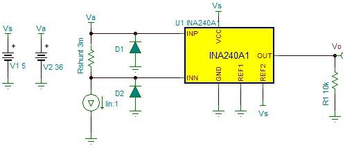
High-Side, Bidirectional Current-Sensing Circuit with Transient Protection
Design Goals
| Input | Output | Supply | Standoff and Clamp Voltages | EFT Level | |||||
|---|---|---|---|---|---|---|---|---|---|
| IinMin | IinMax | VoMin | VoMax | Vs | GND | Vref | Vwm | Vc | Vpp |
| –40 A | 40 A | 100 mV | 4.9 V | 5 V | 0 V | 2.5 V | 36 V | 80 V | 2 kV 8/20 µs |
Design Description
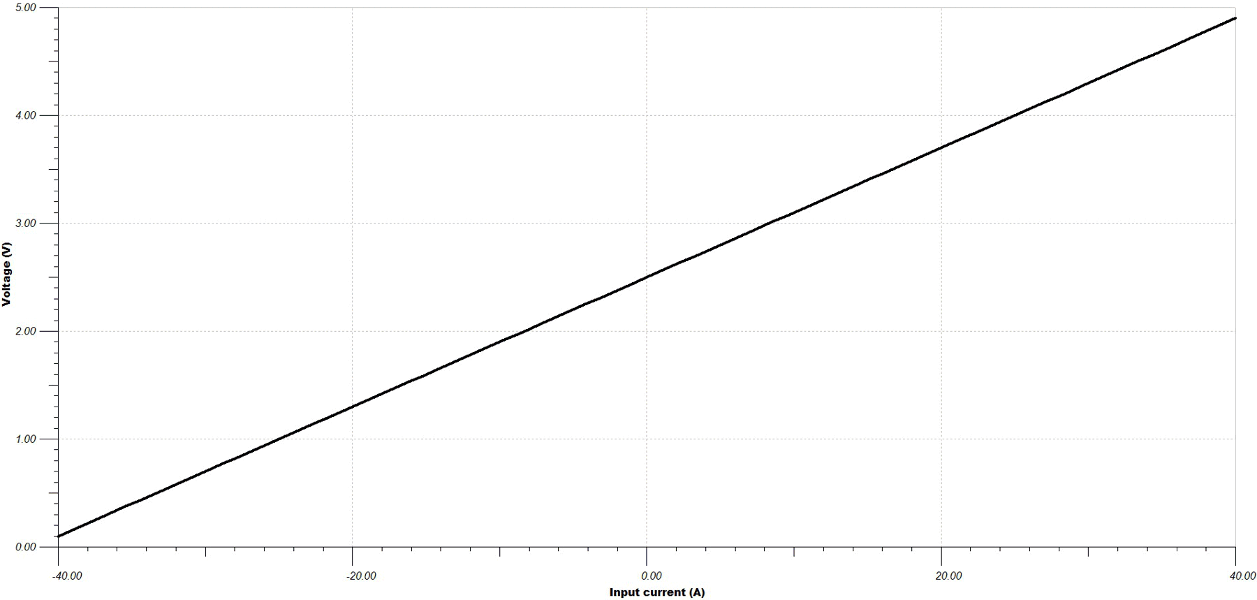
This high-side, bidirectional current sensing solution can accurately measure current in the range of –40 A to 40 A for a 36 V voltage bus. The linear voltage output is 100 mV to 4.90 V. This solution is also designed to survive IEC61000-4-4 level 4 EFT stress (Voc = 2 kV; Isc = 40 A; 8/20 µs).
Design Notes
- This solution is targeted toward high-side current sensing.
- The sense resistor value is determined by minimum and maximum load currents, power dissipation and Current Shunt Amplifier (CSA) gain.
- Bidirectional current sensing requires an output reference voltage (Vref). Device gain is achieved through internal precision matched resistor network.
- The expected maximum and minimum output voltage must be within the device linear range.
- The TVS diode must be selected based on bus voltage, the CSA common-mode voltage specification, and EFT pulse characteristics.
Design Steps
- Determine the maximum output swing:
- Determine the maximum value of the sense resistor based on maximum load current, swing and device gain. In this example, a gain of 20 was chosen to illustrate the calculation, alternative gain versions may be selected as well:
- Calculate the peak power rating of the sense resistor:
- Determine TVS standoff voltage and clamp voltage:
- Select a TVS diode.
For example, SMBJ36A from Littelfuse™ satisfies the previous requirement, with peak pulse power of 600 W (10/1000 µs) and current of 10.4 A.
- Make sure the TVS diode satisfies the
design requirement based on the TVS operating curve.
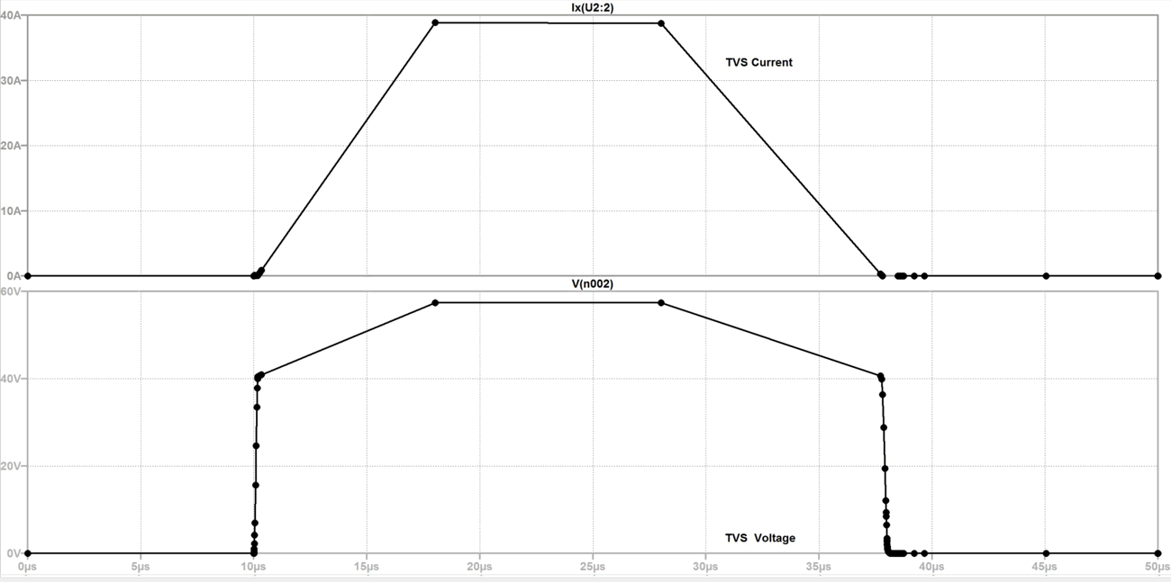
Peak pulse power at given excitation (8/20 µs) is estimated to be around 3.5 kW, which translates to peak pulse current:
This is above the maximum excitation (short circuit) current of 40 A. The select TVS effectively protects the circuit against the specified EFT strike.
Design Simulations
DC Transfer Characteristics
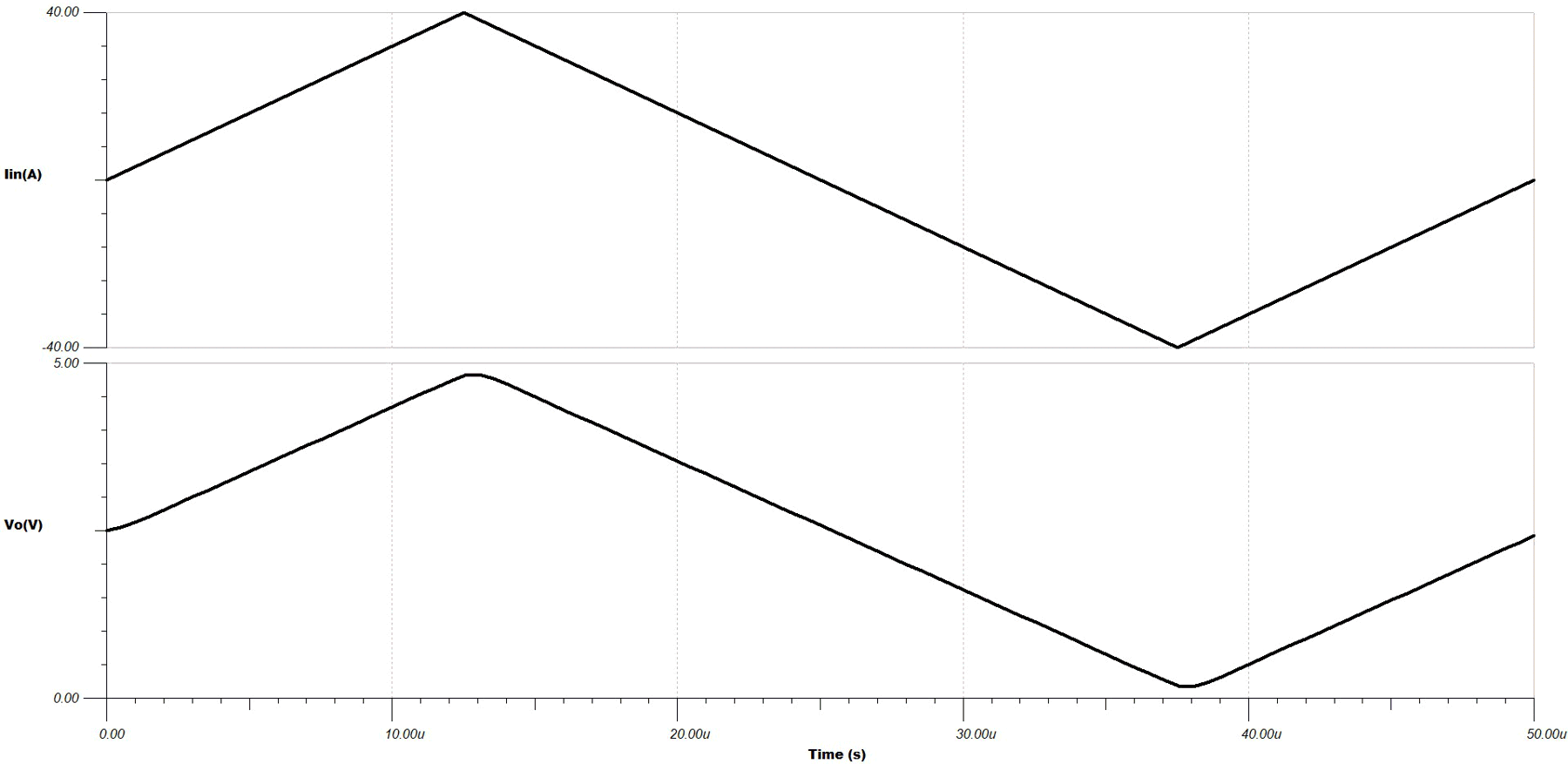
Transient Simulation Results
The output is a scaled version of the input.
TVS Diode Transient Response Under EFT Excitation
Design References
See Analog Engineer's Circuit Cookbooks for TI's comprehensive circuit library.
For more information on transient protection of the current sense amplifiers, see TIDA-00302 and the Current Sense Amplifier Training Videos.
Design Featured Current Sense Amplifier
| INA240A1 | |
|---|---|
| Vs | 2.7 V to 5.5 V |
| VCM | –4 V to 80 V |
| Vos | Rail-to-rail |
| Vos | 5 µV |
| IB | 80 µA |
| BW | 400 kHz |
| Vos Drift | 50 nV/°C |
| INA240A1 | |
Design Alternate
| INA282 | |
|---|---|
| Vs | 2.7 V to 18 V |
| VCM | –14 V to 80 V |
| Vos | 20 µV |
| IB | 25 µA |
| BW | 10 kHz |
| Vos Drift | 0.3 µV/°C |
| INA282 | |
