SBOA356 August 2020 OPA1656 , OPA210 , OPA2210 , OPA2320 , OPA2320-Q1 , OPA320 , OPA320-Q1
4 Cascaded Amplifier Bandwidth
The most common definition for effective bandwidth of a low pass filter (or amplifier in this case) is the frequency where the output voltage drops by 3dB relative to the passband. For a single stage, the cutoff frequency (or pole frequency) can be calculated using equation 1 above. For multiple stages, there are multiple poles to consider.
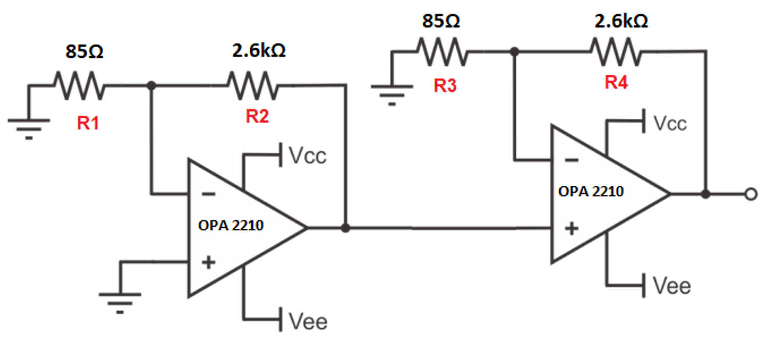
 Figure 4-1 Two-stage cascade
amplifier
Figure 4-1 Two-stage cascade
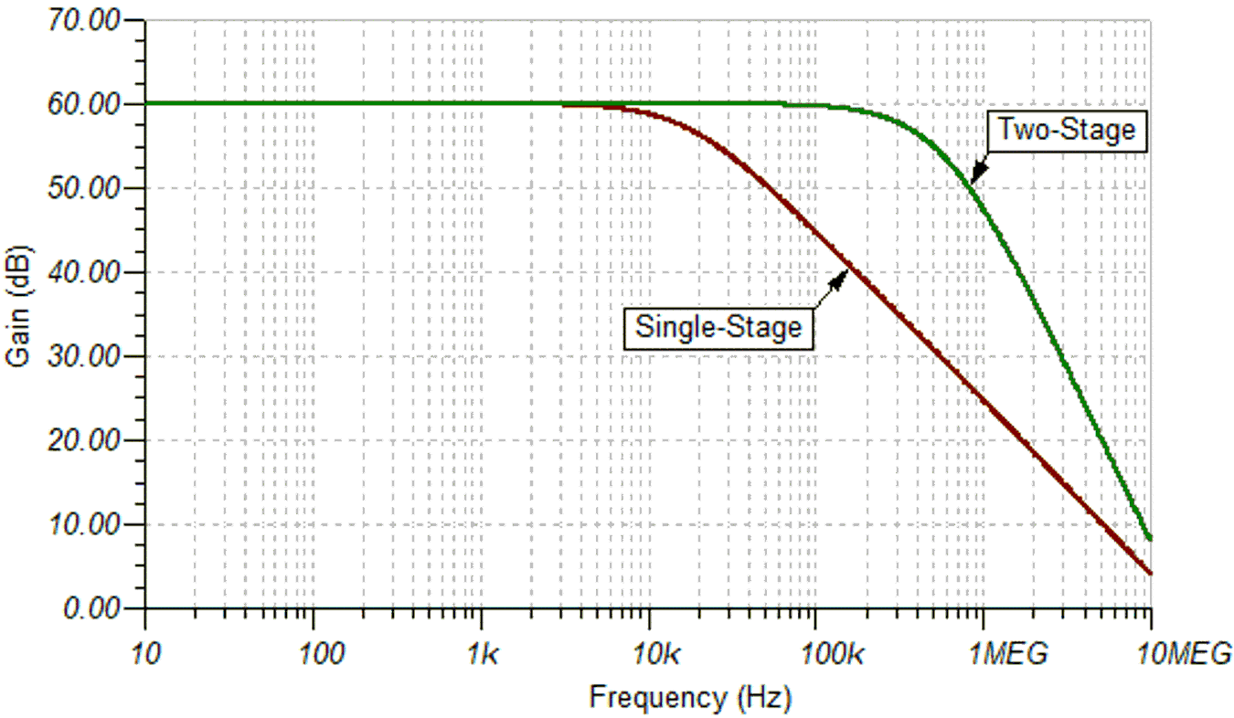
amplifierTo illustrate this, Figure 4-1 shows a two-stage amplifier circuit with a non-inverting gain of 1000 V/V. The gain per stage is 31.6 V/V which corresponds to a bandwidth of about 570kHz for each stage. However, the AC transfer curve in Figure 4-2 shows a drop of 6dB at 570kHz because there are two poles at this frequency, each contributing -3dB to the curve. Each pole also contributes -20dB per decade of roll-off, so the more stages in an amplifier circuit, the steeper the roll-off will be. This can be an advantage if a “brick wall” response is desired.
The effective bandwidth of the entire system is slightly less than that of each stage, at 364kHz, but much greater than the bandwidth of the single-stage amplifier.
 Figure 4-2 Frequency response of
two-stage vs one-stage amplifier
Figure 4-2 Frequency response of
two-stage vs one-stage amplifierAn approximation of the total bandwidth of cascaded amplifier stages can be calculated for n stages by:

Where fc is the cutoff frequency for each stage, as calculated by the GBW.
Note that if one stage’s fc is much lower than the other stages, the low fc will dominate the bandwidth of the system.