SBOA571 august 2023 OPA2387 , OPA387 , OPA4387
3 Introducing a Preconditioning Circuit
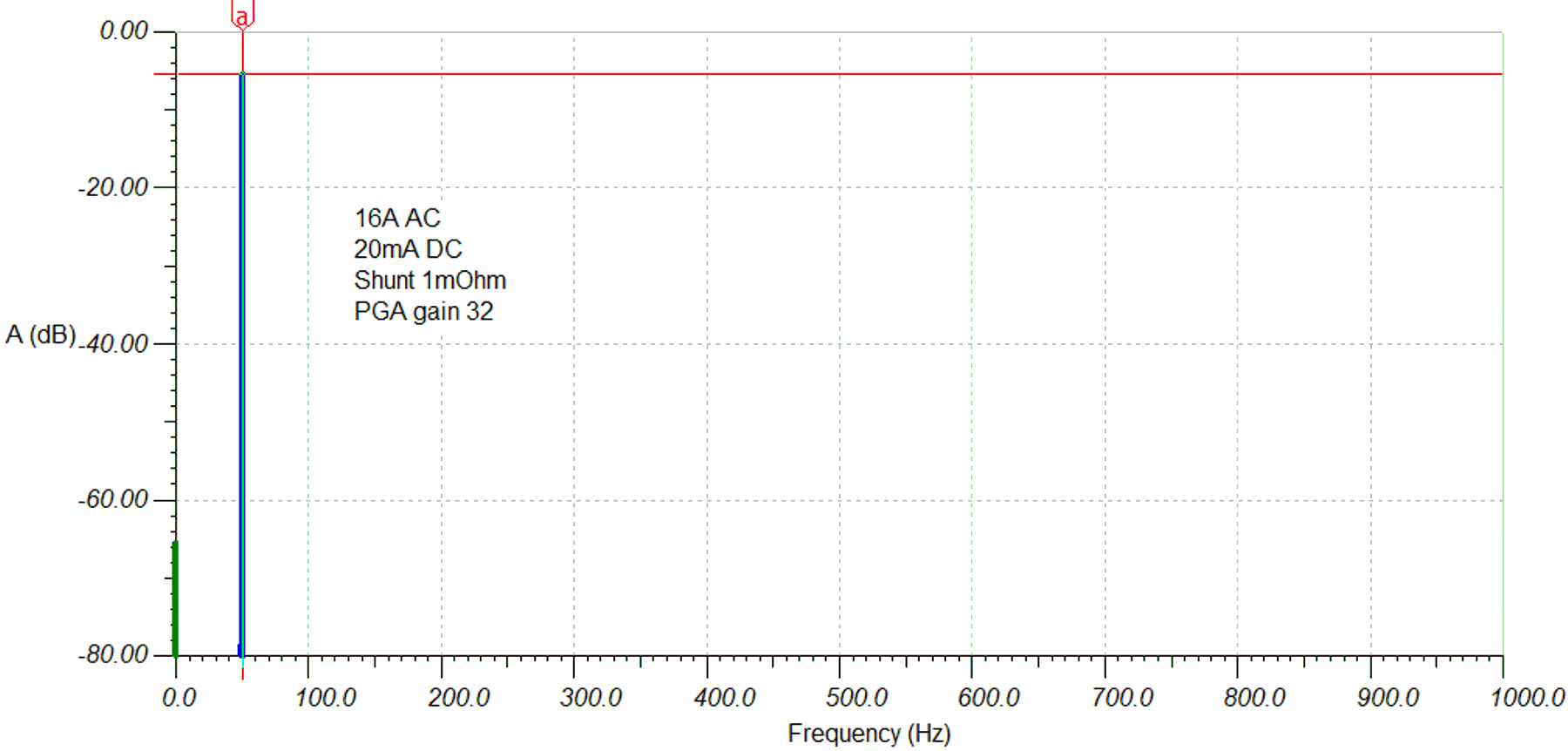
Improvement of the spectrum is achieved by introducing the ADC gain of 32. For simplicity, only the DC energy and the AC fundamental are considered. The AC harmonics follow the gain of the AC fundamental. The gain corrected spectrum is as follows:
 Figure 3-1 FFT DC in AC with PGA Gain = 32, VREF = 1.2 V
To improve the DC in AC sensing and the dynamic range further, introduce a preconditioning circuit in front of the ADC with the following behavior:
- DC gain to amplify the DC value (for example, 8x corresponding to 18 dB)
- AC gain to adjust the AC fundamental to ADC full scale (1.68x corresponding to 4.54 dB)
- Individual DC and AC gain settings
- Flat AC passband already starting at 50 Hz
Such a preconditioning circuit brings the AC fundamental to full scale. The even higher gain for the DC energy increases the DC value by a higher factor and so reduces the required dynamic range and improves the DC energy bin SNR.