SBOA600 July 2024 ISOTMP35
2.4 Step 4: Prepare Each PCB Configuration
For the experiment, three options were tested: the ISOTMP35, an NTC soldered just across the clearance boundary, and an NTC thermally coupled to the copper pad with thermal epoxy, 2 boards each.
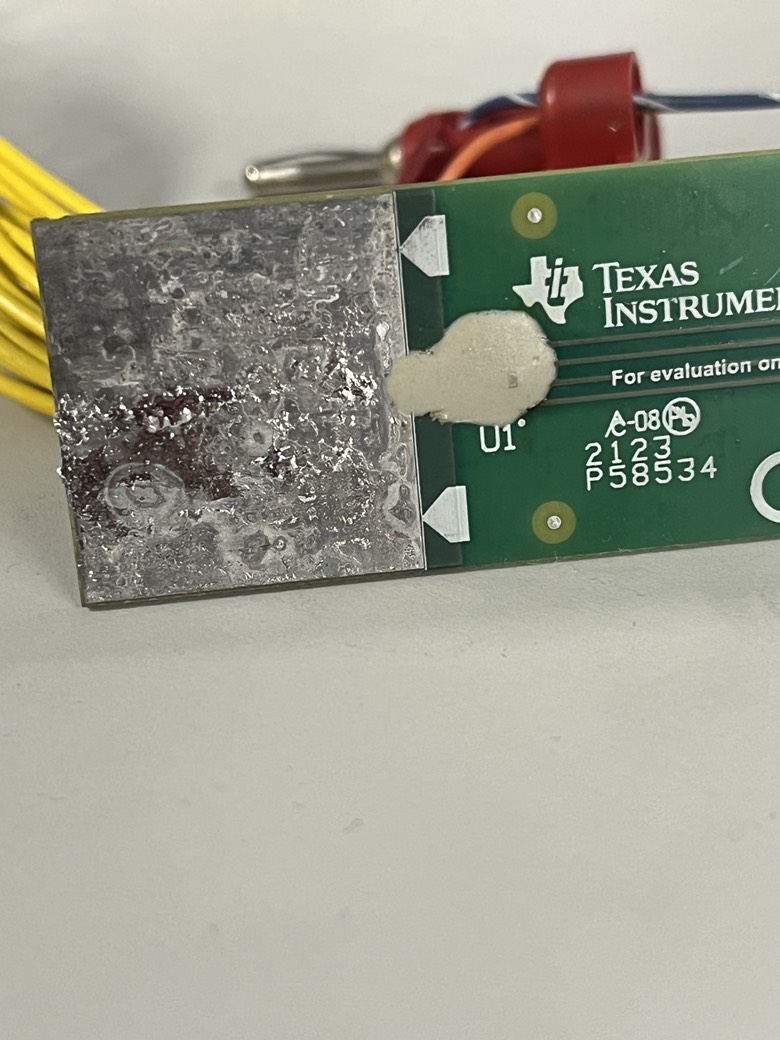
The thermal epoxy chosen was Dycotec Materials Ltd DM-TIM-15340-SYP, which is a thermal epoxy with a thermal conductivity of 3.7W/mK. While this is less than the 400W/mK conductivity of a direct copper connection, it is still a significant improvement over the 0.2W/mK conductivity of FR4 alone.
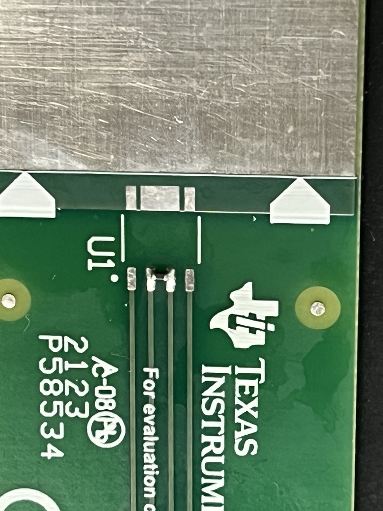
 Figure 2-7 NTC Soldered onto Test
PCB, Across Minimum Clearance
 Figure 2-8 NTC with Cured Thermal
Epoxy