SBOA600 July 2024 ISOTMP35
2.3 Step 3: Submerge the Copper Pad
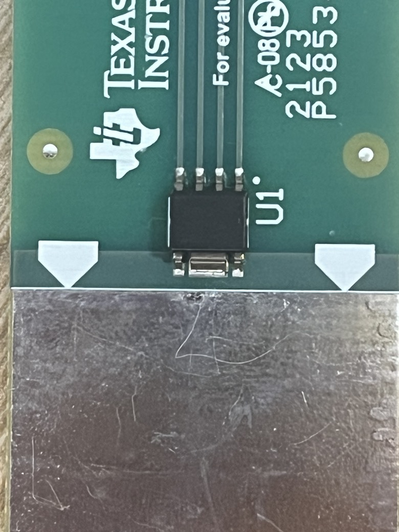
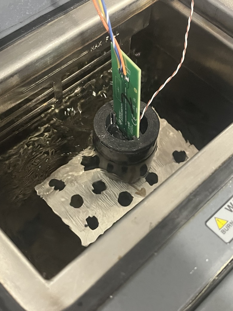
The liquid gallium rises exactly to the edge of the copper pad, marked by the white arrows. The copper pad extends under the solder mask, up to the edge of the package (marked by the line inside the white arrows). The ISOTMP35 is thermally connected to the copper pad via being soldered to it. However, no part of the ISOTMP35 package can actually make direct contact with the liquid gallium. This is done to make sure all the thermal energy the ISOTMP receives comes from the thermal conductivity of the copper, not the liquid gallium pouring right onto the sensor.
 Figure 2-4 PCB Layer View of Test
PCB
 Figure 2-5 ISOTMP35 Mounted on Test
PCB
 Figure 2-6 Test PCB Placed in Liquid
Gallium for Thermal Response Test