SBOU113A June 2011 – January 2023
- INA226EVM Rev A Model User's Guide and Software Tutorial
- 1Trademarks
- 2Overview
- 3INA226EVM Hardware Setup
- 4INA226EVM Hardware
- 5INA226EVM Software Setup
- 6INA226EVM Software Overview
- 7INA226EVM Documentation
- 8Revision History
6.2.1 I2C Address Selection
The INA226 device has a flexible I2C address configuration that allows for multiple devices to be on the same I2C lines. By moving the A0 and A1 addresses on jumpers J3-J6 to either GND, VS, SDA or SCL, the INA226 can be changed to a total of 16 I2C addresses as shown in Table 6-1.
Table 6-1 INA226 I2C Address Configuration
| A1 | A0 | TARGET ADDRESS |
|---|---|---|
| GND | GND | 1000000 |
| GND | VS+ | 1000001 |
| GND | SDA | 1000010 |
| GND | SCL | 1000011 |
| VS+ | GND | 1000100 |
| VS+ | VS+ | 1000101 |
| VS+ | SDA | 1000110 |
| VS+ | SCL | 1000111 |
| SDA | GND | 1001000 |
| SDA | VS+ | 1001001 |
| SDA | SDA | 1001010 |
| SDA | SCL | 1001011 |
| SCL | GND | 1001100 |
| SCL | VS+ | 1001101 |
| SCL | SDA | 1001110 |
| SCL | SCL | 1001111 |
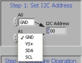
Figure 6-3 shows how to configure the I2C addresses. Click either the A0 or A1 box and select how the hardware is configured on the EVM. Failure to select the correct address prevents the INA226 device from communicating with the software.
 Figure 6-3 Setting the I2C Address