SBOU128B february 2013 – july 2023 INA231
- 1
- INA231EVM Evaluation Board and Software Tutorial
- Trademarks
- 1Overview
- 2INA231EVM Hardware
- 3INA231EVM (Rev A) Hardware Setup
- 4INA231EVM Software Setup
- 5INA231EVM Software Overview
- 6INA231EVM Documentation
- 7Revision History
5.2.2 Configure Operating Mode
The second step of the INA231EVM configuration process allows the user to set the operating mode and the averaging mode.
The operating mode allows the user to restrict the amount of calculations done within the INA231 by changing the conversion to be triggered or continuous, or by shutting down the part altogether. When the device is operating in triggered mode, the device only performs conversions when the operating mode is set and the Write All Reg button at the top of the screen is selected. After the mode changes and Write All Reg is selected, the user must select the Read All Reg button to see the changes on the device reflected in the software.
When the INA231 is operating in continuous mode, conversions are performed directly after the previous conversion is complete. When the INA231EVM software is in continuous mode, the user can click the Read All Reg button to update the software at any time.
Power-down mode stops all conversions from taking place until the operating mode changes again. The device remains attached to power but draws minimal current and does not perform any conversions.
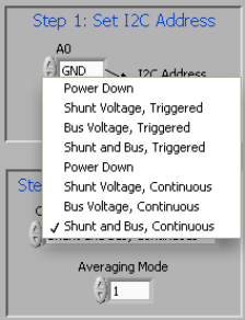
All three operating modes can also be limited to only measuring certain components of the device, as shown in Figure 5-4. It is important to note that for complete functionality of the INA231, the user must choose a configuration with Shunt and Bus configuration. Failure to choose Shunt and Bus configuration disables a considerable portion of the unit functionality as discussed in the INA231 data sheet.
 Figure 5-4 Configuring Operating Mode
The Configure Operation step also contains a drop-down box to select Averaging Mode. The user can set up the INA231 to take the average of several measurements before storing the value of the measurements in the register table.