SBOU180B november 2016 – july 2023 INA260
3.3 Connecting the Hardware
To minimize risk of potential electrical shock hazard, be sure the EVM is full deenergized.
Before connecting the boards, make sure the high current lug connectors (T1 and T2) are tightly secured to the EVM PCB for low contact resistance. To minimize risk of potential electrical shock hazard, deenergize EVM followed by use of a screw-driver, while clasping the nut on the PCB bottom side with a crescent wrench.
It may be necessary to uninstall the nylon standoffs near the lug connectors before manipulating the fasteners to avoid damaging them.
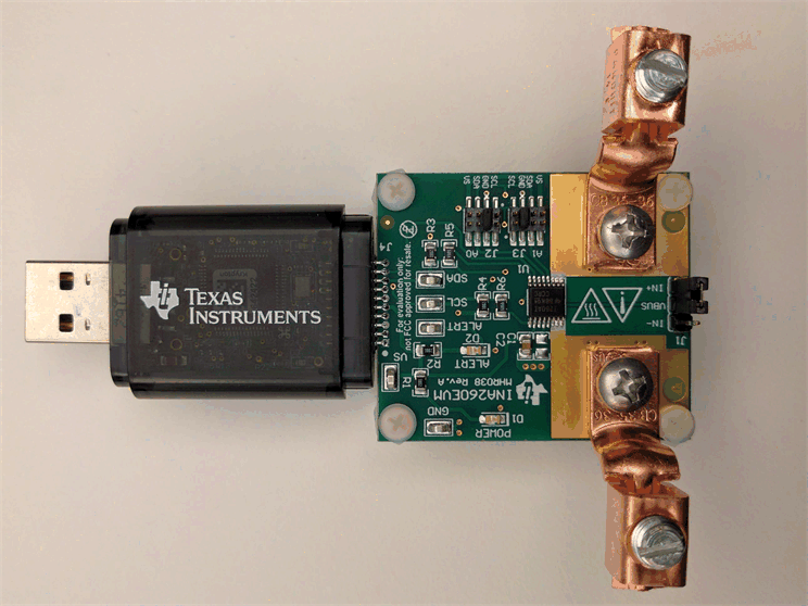
Connect the INA260EVM to the SM-USB-DIG board in the proper orientation, as shown in Figure 3-4. Make sure that the two connectors are completely pushed together; loose connections can cause intermittent operation.
 Figure 3-4 INA260EVM and SM-USB-DIG Connected in Proper Orientation
Next, with the output disabled, connect the input current source to the EVM via T1 and T2, as shown in Figure 3-5.
The lug connectors can accommodate wire sizes up to #6-AWG.
Also be sure to connect the low-side terminal of the input current source to EVM ground (GND) using one of the test points. This step is important to obtain accurate VBUS measurements.
Lastly, connect the SM-USB-DIG to the computer, using the included USB extender cable if necessary. At this point the SM-USB-DIG powers on, but the EVM does not.
The power supply to the EVM must be enabled from the GUI.
 Figure 3-5 SM-USB-DIG Powers on When Connected to a Computer