SBOU257 June 2021 PGA2500
6.2 Using the GUI
Connect the MSP-EXP430F5529LP to the PGA2500EVMV2 board. Connect this to the computer via the USB cable and launch the GUI to automatically flash the microcontroller and adjust all programmable functions. Successful flash can be visually confirmed by GPO LEDs flashing in sequence. Manually set the COM port in the GUI composer to the COM port titled Microsoft after the successful flash by clicking File → Options → Serial Port.
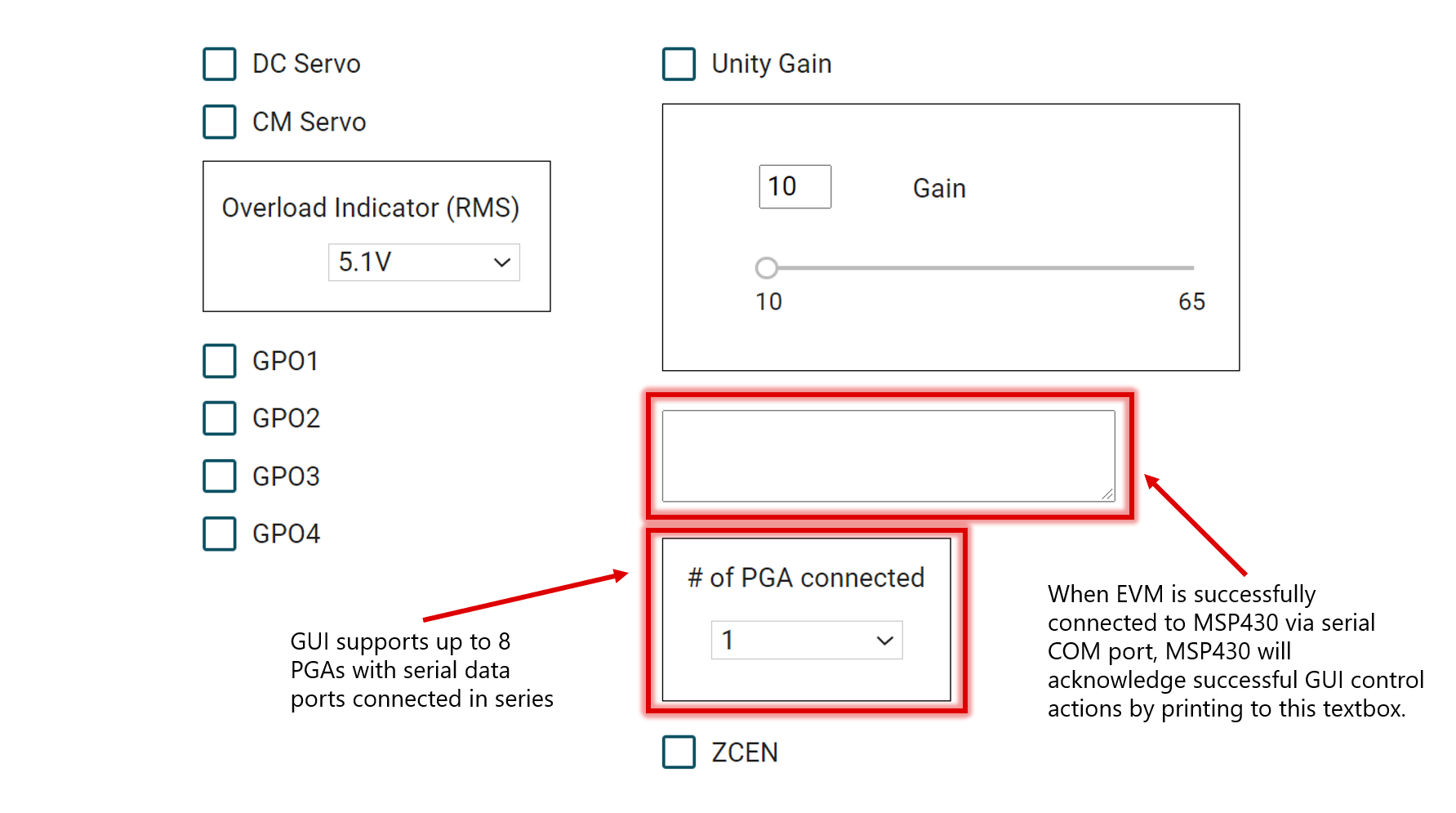
When successfully connected to the microcontroller via serial COM port, the MSP430 will acknowledge successful GUI control actions by printing to this textbox, shown in Figure 6-1:
 Figure 6-1 PGA2500EVMV2 GUI With Programmable Functions