SBOU312 august   2023 ISOTMP35 , ISOTMP35-Q1


  1.   1
  2.   Description
  3.   Get Started
  4.   Features
  5.   Applications
  6.   6
  7. 1Evaluation Module Overview
    1. 1.1 Introduction
    2. 1.2 Kit Contents
    3. 1.3 Specification
    4. 1.4 Device Information
    5. 1.5 General Texas Instruments High Voltage Evaluation (TI HV EVM) User Safety Guidelines
  8. 2Hardware
    1. 2.1 Overview
    2. 2.2 High Voltage Connection Setup Guide
      1. 2.2.1 Detaching the Sensor
      2. 2.2.2 Attaching Sensor Section to High Voltage Heat Source
    3. 2.3 Perforations
    4. 2.4 Status LEDs & Subregulator
    5. 2.5 Programming Header
    6. 2.6 Pushbutton Switch
    7. 2.7 RC Filter
  9. 3Software
    1. 3.1 Software Download
      1. 3.1.1 Online Software
      2. 3.1.2 Offline Software
    2. 3.2 Home Tab
    3. 3.3 Data Capture Tab
    4. 3.4 Collateral Tab
  10. 4Hardware Design Files
    1. 4.1 ISOTMP35BEVM Schematic
    2. 4.2 PCB Layout
    3. 4.3 Bill of Materials
  11. 5Additional Information
    1.     Trademarks

Data Capture Tab

The Data Capture tab automatically begins making temperature measurements. The data displays on a graph that scales with the temperature readings with recorded temperature on the y-axis, and measurement count on the x-axis. The default capture rate is 1 measurement per second. The drop-down menu allows the user to choose a different measurement rate, with the following options:

  • Off
  • As fast as possible
  • Every 500 ms
  • Every 1 s
  • Every 5 s
  • Every 10 s
  • Every 60 s

The SAVE START and SAVE STOP buttons enable the user to log the EVM temperature results in a .csv file. When SAVE START is selected, the file begins downloading, and downloading ends when SAVE STOP is selected.
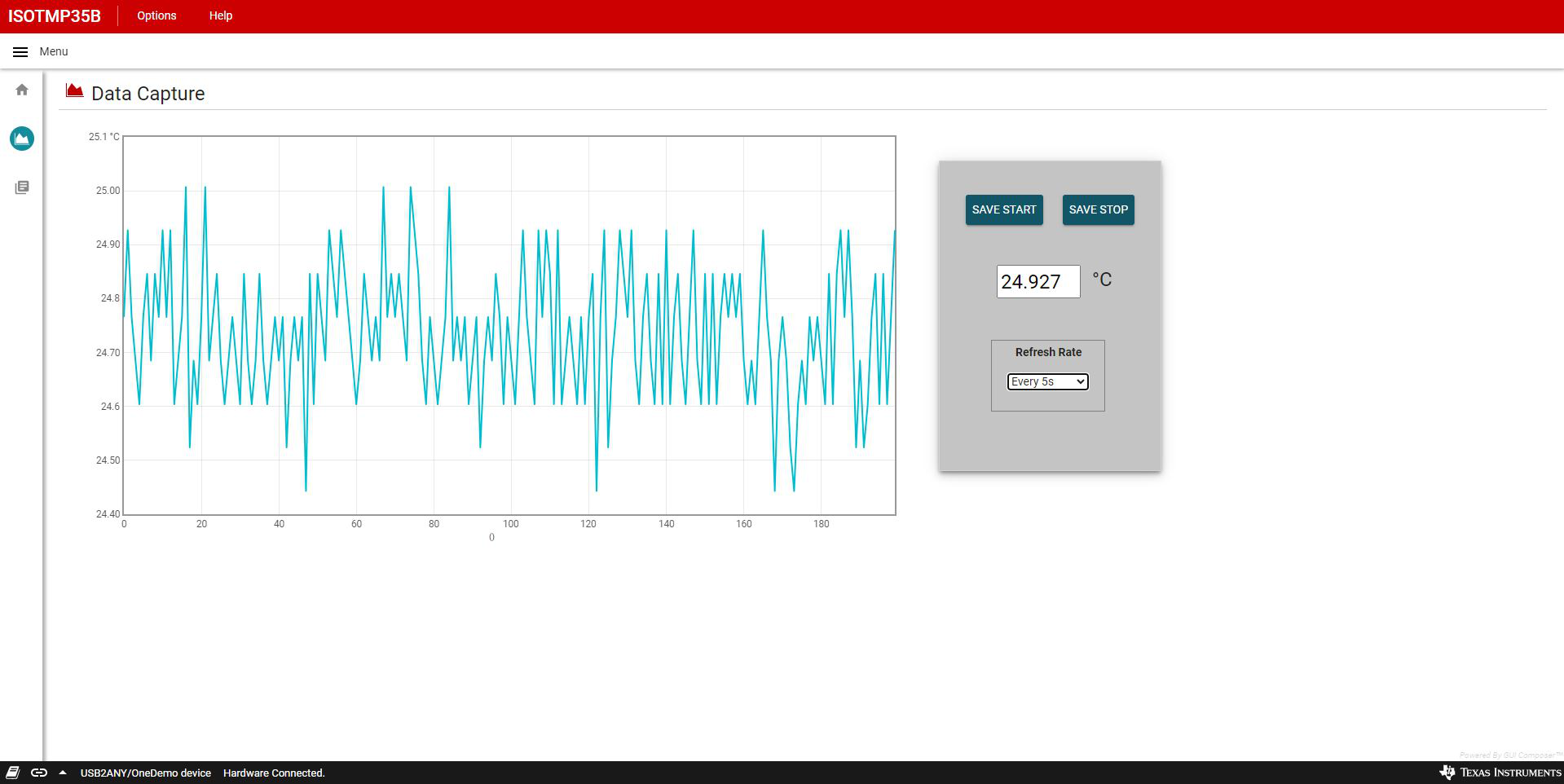
GUID-20230810-SS0I-XJD1-F9F0-DZHNQJTWQFMQ-low.png Figure 3-3 Data Capture Tab