SBVU059A December 2019 – September 2023
- 1
- 2
- Trademarks
- 1Introduction
-
2EVM Setup
- 2.1
Input/Output Connectors and Jumper Descriptions
- 2.1.1 J1 – VIN
- 2.1.2 J2 – VIN
- 2.1.3 J3 – EN
- 2.1.4 J4 – VOUT
- 2.1.5 J5 – PG
- 2.1.6 J6 – VOUT
- 2.1.7 J7 – BIAS
- 2.1.8 J8 – GND
- 2.1.9 J9 – GND
- 2.1.10 J10 -- GND
- 2.1.11 J11
- 2.1.12 J12
- 2.1.13 TP1 – VIN
- 2.1.14 TP2 – VEN
- 2.1.15 TP3 – PG
- 2.1.16 TP4 – VOUT
- 2.1.17 TP5 – VBIAS
- 2.1.18 TP6 – GND
- 2.1.19 TP7 – GND
- 2.1.20 TP8 – GND
- 2.1.21 TP9 – GND
- 2.2 Soldering Guidelines
- 2.3 Equipment Connection
- 2.1
Input/Output Connectors and Jumper Descriptions
- 3Operation
- 4PCB Layout
- 5Schematic
- 6Bill of Materials
- 7Revision History
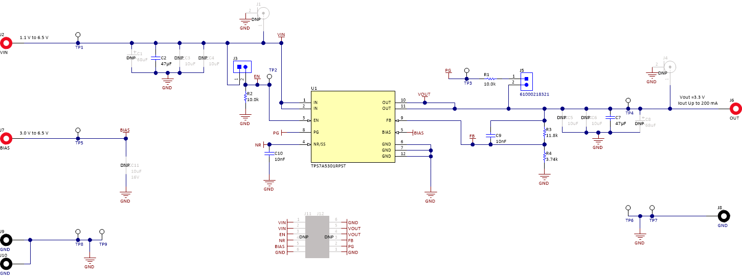
5 Schematic
Figure 5-1 is the schematic for this EVM.
 Figure 5-1 TPS7A53EVM-031 Schematic