SCEA147 September 2024 TXB0104 , TXB0302 , TXB0304
3.1.1 Cable Length Impact - Bench Findings
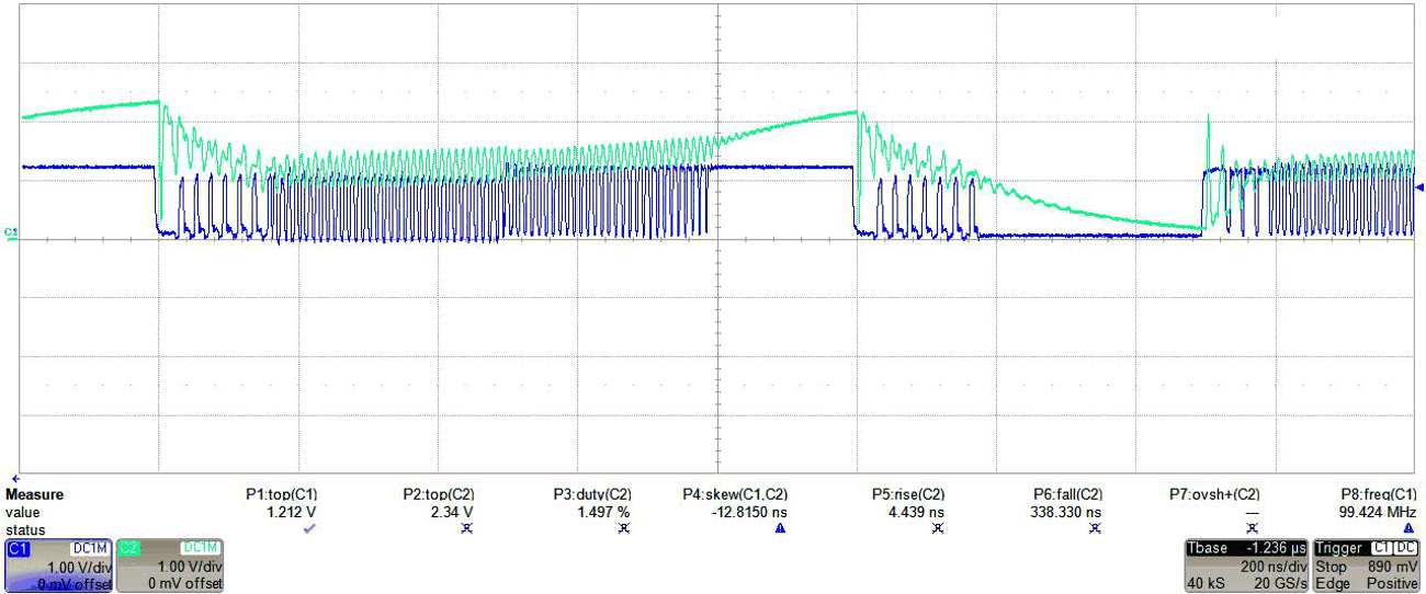
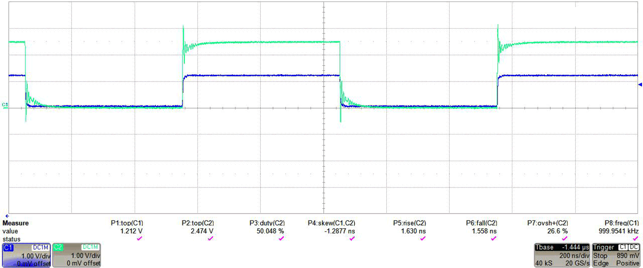
Shown are bench waveforms captured with TXB0304 connected to a 20+ in. and 4 in. cable length. Note the same input conditions were applied to both setups.
 Figure 3-3 TXB0304, 1.2V Input (Dark Blue) to 2.5V Output (Teal) With 20+in. Cable
 Figure 3-4 TXB0304, 1.2V (Dark Blue) to 2.5V Output (Teal) With 4 in. Cable
From the waveform captured in the 20+in. cable above, the input (Dark Blue) oscillates due to unintentional re-triggering of the one-shots at both the input and output sides. Recall that TXB architecture is similar to a buffer loop, with I/Os always being redriven to a known and similar state. When paired with long cabling however, the I/Os result in different logic states due to the timing delay caused by the 20+in. cable. The result is similar to the observed oscillations.
When the setup was swapped to a shorter cable (4in.) in Figure 3-4, the output signal was now more easily interpreted with no oscillations.