SCEA147 September 2024 TXB0104 , TXB0302 , TXB0304
3 Common Design Challenges
Recall that the TXB0104 and TXB0304 have internal one-shot circuitry, hence when paired with excessive loading at the outputs (long traces, connectors, and lumped capacitance), the output signal integrity will be impacted.
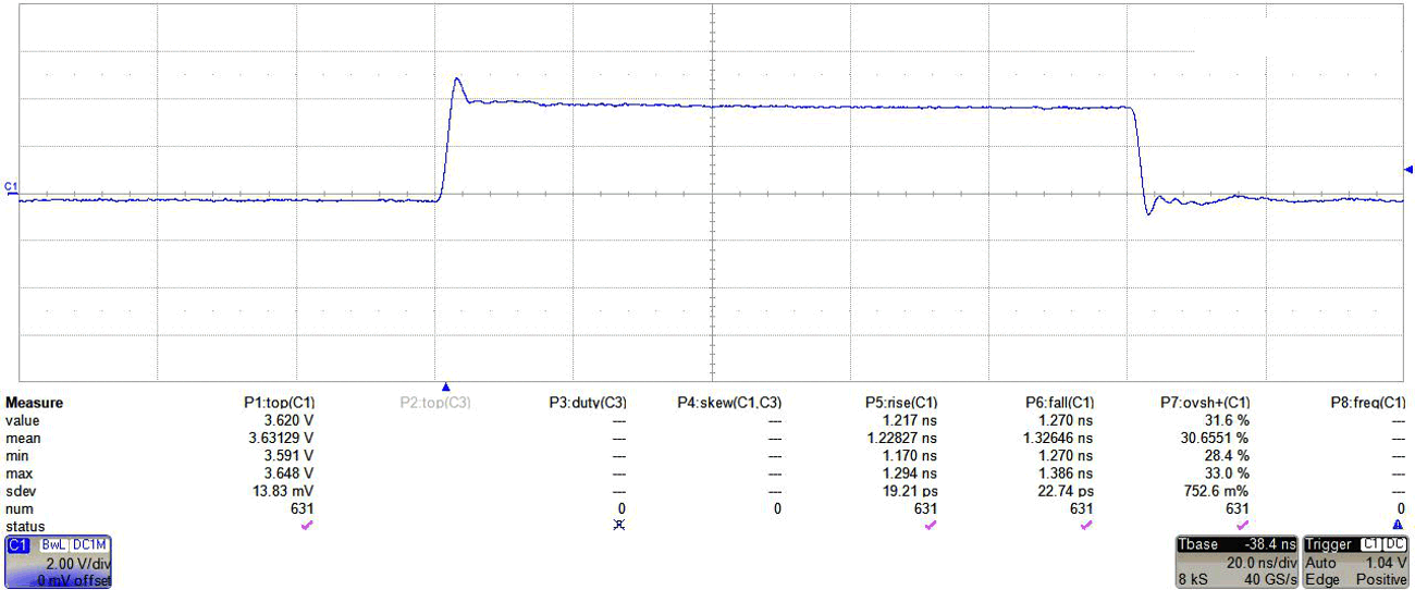
Their one-shot impedance are also different as shown in Table 2-1. If both devices are used under identical setups with similar output load conditions, the TXB0104 can be seen with improved signal integrity over the TXB0304 due to the better impedance match from the one-shot to the output load. As an example, the waveforms captured below in Figure 3-1 and Figure 3-2 show the 3.6V output signal with 15pF lumped capacitance at the TXB0104's output compared to the TXB0304's output. Observe the differences in rise and fall times (tr/tf) in relation to the overshoot % of both devices.
 Figure 3-1 TXB0104, 3.6V Output Signal: tr /
tf < 3.7ns With 2.6 % Overshoot
 Figure 3-2 TXB0304, 3.6V Output Signal: tr /
tf < 1.3ns With 31.6 % Overshoot
Figure 3-2 TXB0304, 3.6V Output Signal: tr /
tf < 1.3ns With 31.6 % OvershootThe stronger output impedance of the TXB0304 results in a higher overshoot when compared to the TXB0104. To resolve this, proper impedance matching techniques with the TXB0304 may be used as discussed in the below section Section 3.2.