SCEU030A August   2024  – December 2024 TPLD1201

PRODUCTION DATA  

  1.   1
  2.   Description
  3.   Get Started
  4.   Features
  5.   Applications
  6.   6
  7. 1Evaluation Module Overview
    1. 1.1 Introduction
    2. 1.2 Kit Contents
    3. 1.3 Specification
    4. 1.4 Device Information
  8. 2Hardware
    1. 2.1 Functional Blocks
      1. 2.1.1 Test Points
      2. 2.1.2 Programmer Header Block (P1)
      3. 2.1.3 External Connection Header Block
      4. 2.1.4 GPI Protection Block
      5. 2.1.5 DGS Socket
    2. 2.2 GPIO Testing Blocks
      1. 2.2.1 LED Blocks
      2. 2.2.2 Switch Blocks
      3. 2.2.3 LED/Potentiometer Blocks
  9. 3Software
    1. 3.1 Using the TPLD1201-DGS-EVM
      1. 3.1.1 Equipment Needed for Programming
      2. 3.1.2 Installing Software
    2. 3.2 Configuring a TPLD Device
      1. 3.2.1 TPLD1201-DGS-EVM Setup for Programming
      2. 3.2.2 Inserting a TPLD1201DGS into the DGS Socket
      3. 3.2.3 Connecting the TPLD1201-DGS-EVM to a TPLD-PROGRAM Board
      4. 3.2.4 Temporarily Configuring a TPLD Device
      5. 3.2.5 Permanently Programming a TPLD Device
    3. 3.3 Testing with the TPLD1201-DGS-EVM Demo
      1. 3.3.1 TPLD1201 Demo Circuit
      2. 3.3.2 Testing the Demo
  10. 4Hardware Design Files
    1. 4.1 Schematics
    2. 4.2 PCB Layout
      1. 4.2.1 PCB Overview
    3. 4.3 Bill of Materials
  11. 5Additional Information
    1. 5.1 Trademarks
  12. 6Revision History

Permanently Programming a TPLD Device

This section covers using InterConnect Studio to permanently program a TPLD1201. Permanently programmed devices retain the configuration the devices are programmed with after power is reset.

Permanently programmed devices must not be permanently programmed again to avoid damaging the device.

  1. Open the desired configuration to be permanently programmed in the TPLD1201 in InterConnect Studio.
  2. Open the Configure Settings by selecting the three dots icon beside the CONFIGURE TPLD1201 button.
  3. Select Permanently Configure Device. If using a TPLD-PROGRAM to power the EVM, then leave the Power Source as Programmer. Select OK.
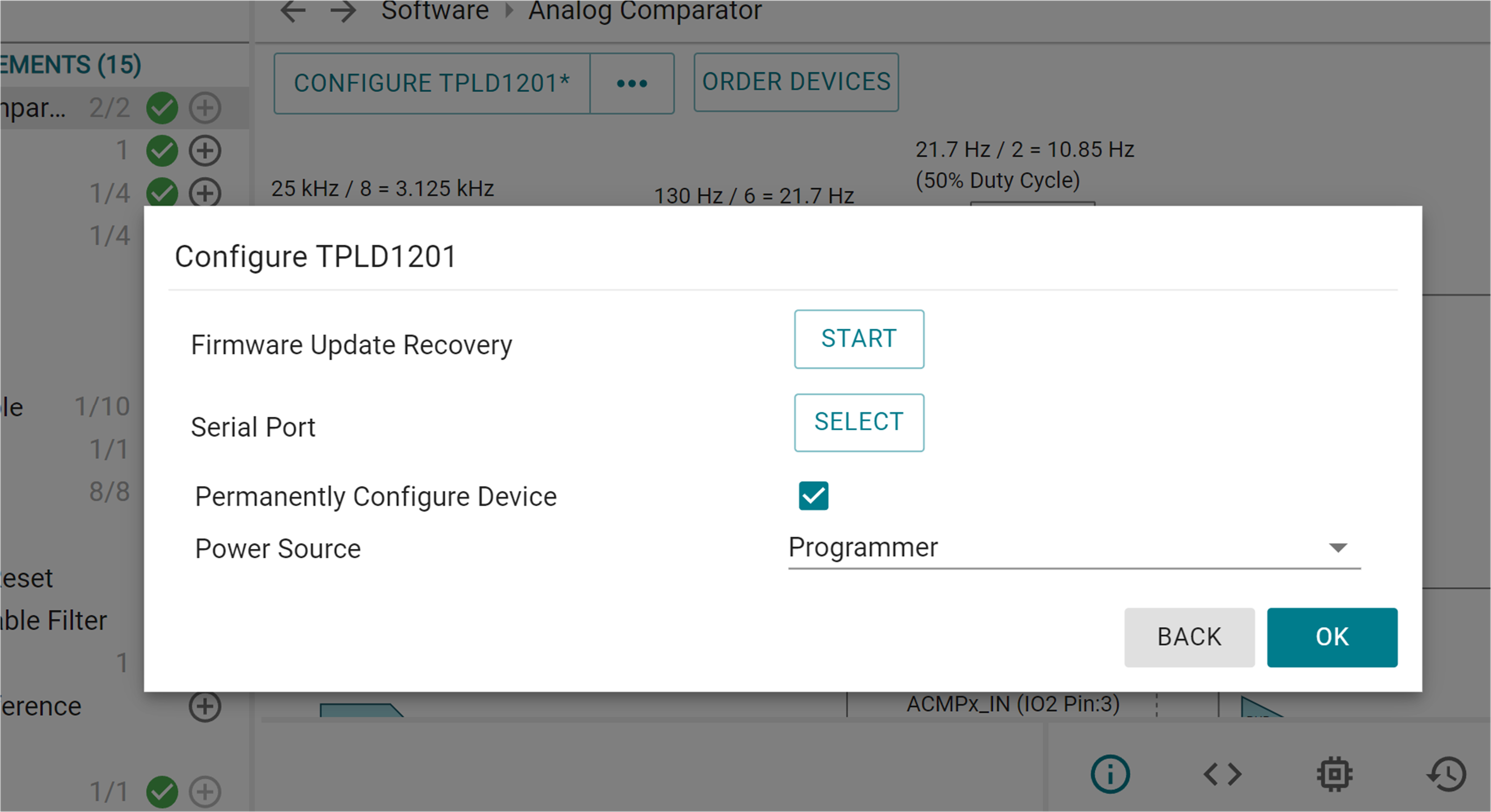
    TPLD1201-DGS-EVM Permanent Programming
                            in ICS Figure 3-7 Permanent Programming in ICS
  4. Select the serial port connected to the TPLD-PROGRAM, then select OK again.
    1. Some LEDs on the TPLD1201-DGS-EVM can flash during the programming sequence, which is normal.
    2. If the configuration fails, then check the connections between the EVM and the computer, make sure SW3 is ON, check the connection between the TPLD device and the socket contacts, and retry.
  5. Remove power from the EVM before removing the permanently programmed TPLD1201.