SCLS554D January   2004  – June 2024 SN74HC4851-Q1

PRODUCTION DATA  

  1.   1
  2. Features
  3. Applications
  4. Description
  5. Pin Configuration and Functions
  6. Specifications
    1. 5.1 Absolute Maximum Ratings
    2. 5.2 Thermal Information: SN74HC485x-Q1
    3. 5.3 Recommended Operating Conditions
    4. 5.4 Electrical Characteristics
    5. 5.5 Timing Characteristics
    6. 5.6 Injection Current Coupling
  7. Parameter Measurement Information
  8. Detailed Description
    1. 7.1 Functional Block Diagram
  9. Application and Implementation
    1. 8.1 Application Information
  10. Device and Documentation Support
    1. 9.1 Receiving Notification of Documentation Updates
    2. 9.2 Support Resources
    3. 9.3 Trademarks
    4. 9.4 Electrostatic Discharge Caution
    5. 9.5 Glossary
  11. 10Revision History
  12. 11Mechanical, Packaging, and Orderable Information

Application Information

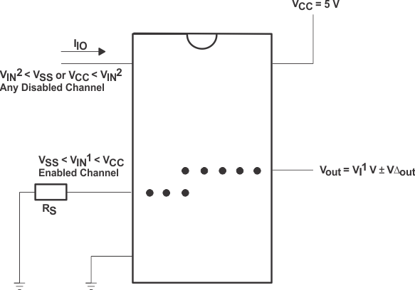
SN74HC4851-Q1 Injection-Current Coupling Specification Figure 8-1 Injection-Current Coupling Specification
SN74HC4851-Q1 Alternate
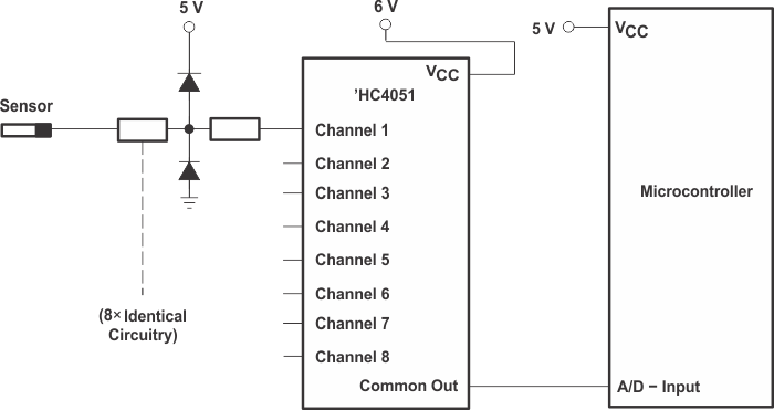
                    Solution Requires 32 Passive Components and One Extra 6-V Regulator to Suppress
                    Injection Current Into a Standard ’HC4051 Multiplexer Figure 8-2 Alternate Solution Requires 32 Passive Components and One Extra 6-V Regulator to Suppress Injection Current Into a Standard ’HC4051 Multiplexer
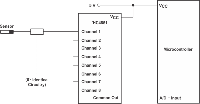
SN74HC4851-Q1 Solution
                    by Applying the ’HC4851 Multiplexer Figure 8-3 Solution by Applying the ’HC4851 Multiplexer
SN74HC4851-Q1 Diagram
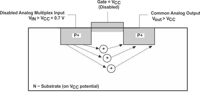
                    of Bipolar Coupling Mechanism (Appears if VIN Exceeds VCC,
                    Driving Injection Current Into the Substrate) Figure 8-4 Diagram of Bipolar Coupling Mechanism (Appears if VIN Exceeds VCC, Driving Injection Current Into the Substrate)