SCPA069 July 2024 TCA4307
3 Crosstalk
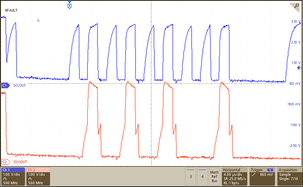
A common way a false edge can be generated is through crosstalk. Typically, in terms of I2C, crosstalk is generated by shared capacitance between two lines (imagine two long parallel running traces on a PCB with little separation) and a fast edge rate. Normally if an I2C line experiences crosstalk, the crosstalk event occurs when either the SDA or SCL line is in a logic HIGH state. This because the signal is more strongly biased when driving a low logic due to the open drain architecture of I2C . A logic high state is set by a pull-up resistor which is much weaker in comparison to an open drain driver. Ron of these open drain drivers are much stronger (have a low value Ron) than the external pull-up resistor to establish the logic high signal. This means in most I2C transactions, the SDA line can be the signal that sees crosstalk since the SDA does not change the state unless SCL is low. The only time this is not true is during a start condition therefore this can be a potential area where a false clock edge can occur if severe enough. If a stuck bus is occurring and crosstalk appears to be present on the SDA line, then checking the beginning of the I2C transaction at the start condition is recommended to rule out crosstalk as the culprit.
 Figure 3-1 Example of Crosstalk
This does not mean the clock line isn’t at risk after a clean start condition is issued, other faster edges near the SCL trace can still induce crosstalk onto the SCL bus during the high period. One of the main takeaways here is to properly layout the I2C traces such that SCL is not too close (parallel) to other traces which have fast edge rates (including SDA). Parallel can also mean high frequency or high current driven traces that run directly beneath the SCL trace.