SGEA001A December   2019  – April 2021 SN74LVC1G125-Q1


  1.   Trademarks
  2. 1Block Diagram
  3. 2Optimizing Gate Driver Control and MCU Communication
  4. 3Logic and Translation Use Cases
    1. 3.1 Logic Use Cases
      1. 3.1.1 Increase Drive Strength
      2. 3.1.2 Gate Driver Control
      3. 3.1.3 Low-Power CAN Wake
    2. 3.2 Voltage Translation Use Cases
      1. 3.2.1 Non-Isolated SPI Communication
      2. 3.2.2 Non-Isolated UART Communication
  5. 4Recommended Logic and Translation Families for On-Board and Wireless Chargers
    1. 4.1 LVC: Low-Voltage CMOS Logic and Translation
    2. 4.2 HCS: Schmitt-Trigger Integrated High-Speed CMOS Logic
  6. 5Revision History

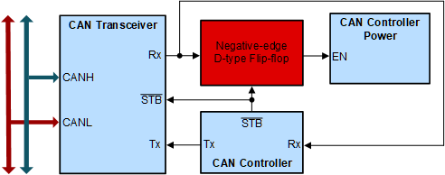
Low-Power CAN Wake

GUID-9F5960F7-152D-4A25-B66A-4702A3E0281D-low.gifFigure 3-3 Using Logic to Enable CAN Controller Power With Wake-Up Pattern
  • Conserve power leaving the CAN controller in a power down state
  • Flexible solution to accommodate any active high or active low enables
  • Trigger immediately after the wake-up pattern is read
  • Look here to find more information about the negative-edge D-type flip-flop