SLAA475A October 2010 – March 2019 MSP430L092
-
MSP430x09x Analog Pool: Feature Set and Advanced Use
- Trademarks
- 1 MSP430x09x Overview
- 2
Analog Pool (A-Pool)
- 2.1 Input Dividers
- 2.2 Internal Reference
- 2.3 Starting and Stopping the A-Pool
- 2.4 Comparator Function
- 2.5 8-Bit DAC Function
- 2.6 8-Bit ADC Function
- 2.7 SVM Function
- 2.8 Use of Multiple Features
- 2.9 Temperature Measurements With the A-Pool
- 2.10 Fractional and Integer Number Use
- 2.11 APINTB and APFRACTB Use With ATBU and EOCBU
- 2.12 A-Pool Trigger Sources
- 2.13 Filtering ADC Conversions With Digital Filters
- 3 Summary
- 4 References
- Revision History
2.4 Comparator Function
To use the A-Pool as a comparator, the multiplexer must be configured correctly and the comparator itself must be enabled. Two flags (CRIFG and CFIFG) are generated for rising and falling edge detection, respectively, when the comparator is in clocked mode. Clocked mode is used when AZCMP bit is set to 1 or the AZSWREQ function is used. In CTEN mode, no rising or falling edge flags are generated, because the flag generation logic is disabled. To observe the comparator status in this mode, the CxOUT bit can be used.
A small digital filter is implemented for deglitching purposes. The user can decide between several filter options, from no filtering up to a majority vote of three out of five samples. The filtering consumes up to five additional comparator clocks and should be selected properly depending on the user application.
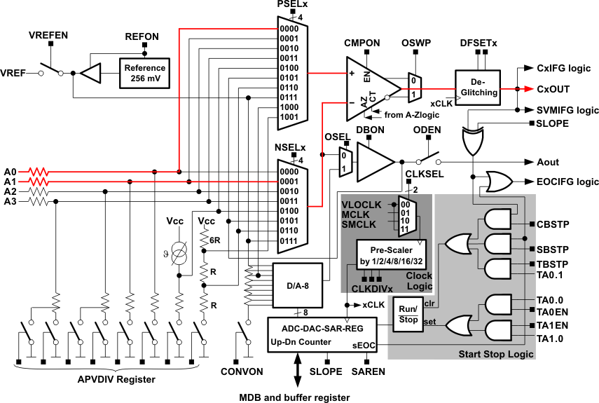
The comparator output signal itself is routed out to a dedicated port pin and can be used for external observations or as an input for additional hardware. To be more flexible, it is also possible to switch out the inverted comparator signal. Based on this signal, several flags such as the EOC flag or the rising and falling edge flags are generated (see Figure 3).
 Figure 3. Example of Comparator Function
 This following code shows how to configure a simple comparator function with A0 and A1 as inputs.
APCTL = APNSEL0;   // Set A0 as pos. input and A1 as neg. input
APCNF = CMPON;     // Switch on comparator
APOMR = AZCMP;     // Set comparator to clocked zero compensated long term comparison
Within this comparison mode it is possible to use the CRIFG and CFIFG flags for interrupt generation and comparator output change reaction.
The comparator is used in the clocked auto-zero compensation mode. This means that every two clock cycles the comparator offset is eliminated within the auto-zero phase. During this time, the comparator does not generate any output. To avoid this dead time, the comparator can be switched into a continuous enable mode, as shown in the following code.
APCTL = APNSEL0;   // Set A0 as pos. input and A1 as neg. input
APCNF = CMPON;     // Switch on comparator
APOMR = CTEN;      // Set comparator into continuous time mode for all operations
Using this mode, it is not possible to use the CRIFG and CFIFG flag, because the comparator is not in a clocked mode. To observe the output of the comparator, the COMPOUT bit can be used.
A clocked mode can be established in several ways. First would be the use of the auto-zero compensation mode, which is the default mode after a reset. Second would be the software request for an auto-zero phase. Third would be an ADC conversion with the implemented SAR logic.