SLAA600E June   2013  – January 2024


  1.   1
  2.   Abstract
  3.   Trademarks
  4. 1Introduction
    1. 1.1 Glossary
    2. 1.2 Conventions
  5. 2Implementation
    1. 2.1 Main
    2. 2.2 Application Manager
      1. 2.2.1 Boot and Application Detection
        1. 2.2.1.1 Force Bootloader Mode
        2. 2.2.1.2 Application Validation
        3. 2.2.1.3 Jump to Application
      2. 2.2.2 Vector Redirection
      3. 2.2.3 Interrupt Vectors in Flash Devices
      4. 2.2.4 Dual Image Support
        1. 2.2.4.1 Jumping to Application in Dual Image Mode
    3. 2.3 Memory Interface (MI)
      1. 2.3.1 Dual Image Support
    4. 2.4 Communication Interface (CI)
      1. 2.4.1 Physical-DataLink (PHY-DL)
        1. 2.4.1.1 I2C
          1. 2.4.1.1.1 Time-out Detection
        2. 2.4.1.2 UART
        3. 2.4.1.3 SPI
        4. 2.4.1.4 CC110x
        5. 2.4.1.5 Comm Sharing
      2. 2.4.2 NWK-APP
        1. 2.4.2.1 BSL-Based Protocol
          1. 2.4.2.1.1 Security
          2. 2.4.2.1.2 BSL-Based Protocol using CC110x
          3. 2.4.2.1.3 Examples Using I2C
          4. 2.4.2.1.4 Examples Using UART or CC110x
  6. 3Customization of MSPBoot
    1. 3.1 Predefined Customizations
  7. 4Building MSPBoot
    1. 4.1 Starting a New Project
      1. 4.1.1 Creating a New MSPBoot Project
        1. 4.1.1.1 MSPBootProjectCreator.pl
        2. 4.1.1.2 Importing Project Spec File in CCS
        3. 4.1.1.3 Modifying Generated Source Code
          1. 4.1.1.3.1 Modifying MSPBoot Main.c
          2. 4.1.1.3.2 Modifying TI_MSPBoot_Config.h
          3. 4.1.1.3.3 Modifying TI_MSPBoot_CI_PHYDL_xxxx_xxx.c
          4. 4.1.1.3.4 Modifying TI_MSPBoot_AppMgr.c
          5. 4.1.1.3.5 Modifying Application Main.c
          6. 4.1.1.3.6 Modifying TI_MSPBoot_Mgr_Vectors_xxxx.c
      2. 4.1.2 Loading Application Code With MSPBoot
        1. 4.1.2.1 Convert Application Output Images
    2. 4.2 Examples
      1. 4.2.1 LaunchPad Development Kit Hardware
      2. 4.2.2 CC110x Hardware
      3. 4.2.3 Building the Target Project
      4. 4.2.4 Building the Host Project
      5. 4.2.5 Running the Examples
  8. 5References
  9. 6Revision History

Convert Application Output Images

The CCS projects can be setup to generate outputs in MSP430 .txt format or Intel .hex format by following Project Properties → MSP430 Hex Utility for more information. Neither file includes a CRC, but one can either be calculated by the host processor or needs to be added manually to the generated file. Regardless of how the CRC is calculated, the application image must be converted to a format useable by the host processor. To make this easier, the software package includes image2C, a Perl script used to convert an MSP430 .txt file or Intel .hex file to a C array.

Location: MSPBoot\Utilities\430 Image Converter\image2C.pl

Syntax:

[] denotes an optional field
image2C.pl 
                [-help]
                -src <src_file>
                -dest <dest_file>
                -struct <array_name>
                [-20_bit]
  • -src <src_file> = Specifies the source file in .txt or .hex format.
  • -dst <dest_file> = Specifies the destination file in .c format.
  • -struct <array_name> = Name of the array in C file. If using the host examples provided in the accompanying software package, TI recommends naming the struct App1 or App2.
  • -20_bit = Optional parameter. Specifies that the files created are compatible with large memory model (20 bit) MSP430 devices. If using a large memory model device, this command is required for the file to be generated correctly. If not specified, single image is assumed.
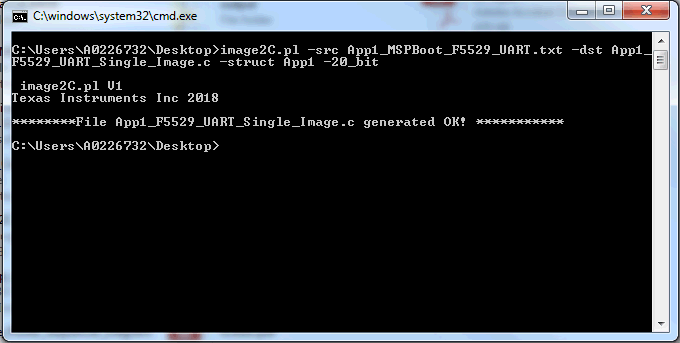
GUID-D6B28E59-5171-4DD5-8423-932BB30584DC-low.pngFigure 4-3 image2C Example
Note:

A Perl interpreter is required to run this script. Visit https://www.perl.org/ to download an interpreter if needed.