SLAA732A February   2017  – April 2021 PGA460 , PGA460-Q1


  1. 1Trademarks
  2. 2Overview
  3. 3External Performance Factors
    1. 3.1 Range Requirements
    2. 3.2 Detectable Target and Objects
    3. 3.3 Ambient Environment
  4. 4Component Selection
    1. 4.1 Sonar Configuration
    2. 4.2 Transducer Selection
    3. 4.3 Driver Selection
    4. 4.4 Passive Tuning
      1. 4.4.1 Impedance Gain-Phase Analyzer
      2. 4.4.2 Tuning Capacitor
      3. 4.4.3 Damping Resistor
      4. 4.4.4 Tunable Transformer
  5. 5PGA460 Parameters
    1. 5.1 Center Frequency
    2. 5.2 Pulse Count
    3. 5.3 Current Limit
    4. 5.4 Time-Varying Gain and Digital Gain
    5. 5.5 Threshold
  6. 6End-of-Line Calibration
    1. 6.1 Transducer Parameters
      1. 6.1.1 Optimal Frequency and Sound Pressure Level Measurements
        1. 6.1.1.1 Frequency Diagnostic Feature of PGA460
        2. 6.1.1.2 External Microphone
  7. 7Revision History

Frequency Diagnostic Feature of PGA460

The PGA460 device offers a feature to measure the ringing-decay frequency of the transducer. The user has the ability to set the start time (FDIAG_START) and window length (FDIAG_LEN) of the frequency measurement to validate the performance and proper tuning of the transducer. In addition, a frequency error feature is implemented in the PGA460 device to signify that the measured transducer frequency is outside of the limits set by the FDIAG_ERR_TH threshold parameter. Both the measured frequency and error status can be read through any of the interface options.
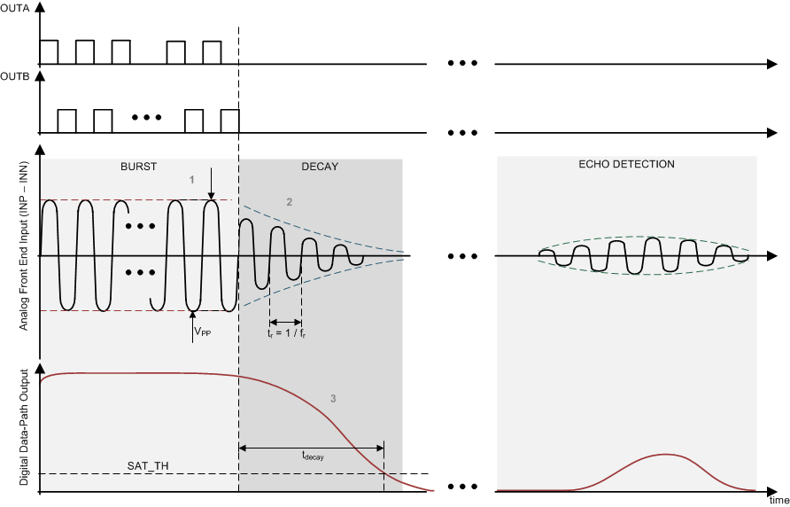
GUID-BC1342F5-CF65-41A5-92D7-3433A379799E-low.gifFigure 6-1 Frequency Diagnostic Timing Diagram