SLAA891B April 2019 – February 2020 MSP430FR2512 , MSP430FR2512 , MSP430FR2522 , MSP430FR2522 , MSP430FR2532 , MSP430FR2532 , MSP430FR2533 , MSP430FR2533 , MSP430FR2632 , MSP430FR2632 , MSP430FR2633 , MSP430FR2633 , MSP430FR2672 , MSP430FR2672 , MSP430FR2673 , MSP430FR2673 , MSP430FR2675 , MSP430FR2675 , MSP430FR2676 , MSP430FR2676
3 Slider
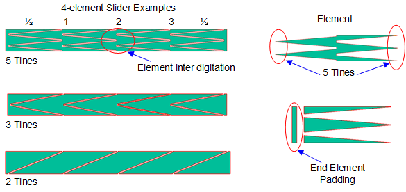
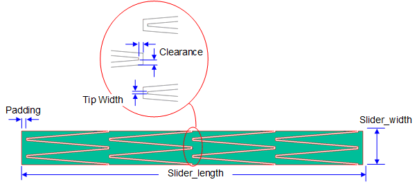
Slider sensors are constructed from overlapping or inter-digitated linear sections of copper referred to as sensor "elements". The number of elements is defined by the script parameter total_elements (see Figure 4). The inter-digitation is created by "tines" that are defined by the script parameter tines. Element tines allow better coupling between electrodes and a better linear response as a finger moves up and down the slider. The left and right ends include a small region referred to as "padding" that is defined by the script width parameter padding. Sliders need at least 3 elements to work properly and rarely need more than 4 elements to provide an adequate linear active area of input. The overall length and width of the slider are defined by the script parameters slider_length and slider_width, respectively.
Two additional sensor attributes are spacing and tip width. The spacing between neighboring electrodes is defined by the script parameter clearance. The width of the tip of each tine is defined by the script parameter tip_width (see Figure 5).

