SLAA891B April 2019 – February 2020 MSP430FR2512 , MSP430FR2512 , MSP430FR2522 , MSP430FR2522 , MSP430FR2532 , MSP430FR2532 , MSP430FR2533 , MSP430FR2533 , MSP430FR2632 , MSP430FR2632 , MSP430FR2633 , MSP430FR2633 , MSP430FR2672 , MSP430FR2672 , MSP430FR2673 , MSP430FR2673 , MSP430FR2675 , MSP430FR2675 , MSP430FR2676 , MSP430FR2676
4 Wheel
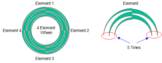
Wheel sensors are constructed from overlapping or inter-digitated curved sections of copper referred to as sensor "elements". The number of elements is defined by the script parameter total_elements. The inter-digitation is created by "tines" that are defined by the script parameter tines (see Figure 6). Element tines allow better coupling between electrodes and a better linear response as a finger moves up and down the slider. Like the slider, the wheel needs a minimum of 3 elements and rarely needs more than 4 elements to provide an good linear input response.
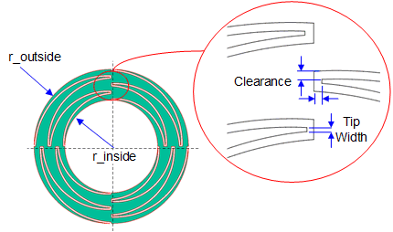
The outside perimeter of the wheel is defined by the script parameter r_outside. The inside perimeter of the wheel is defined by the parameter r_inside. The difference between these two parameters determines the width of the wheel. The spacing between neighboring electrodes is defined by the parameter clearance. The width of the tip of each tine is defined by the script parameter tip_width. The clearance and tip_width parameters determine the level of coupling between any two electrodes (see Figure 7).
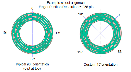
A wheel is typically designed with element 0 located at the top position on the wheel. This position is defined by the parameter start_angle. It is possible to select other orientations if needed (see Figure 8).


