Single-Supply Strain Gauge Bridge Amplifier Circuit with MSP430™ Smart Analog Combo
Design Goals
| Input ViDiff (Vi2 – Vi1) | Output | Supply | ||||
|---|---|---|---|---|---|---|
| ViDiff_Min | ViDiff_Max | VoMin | VoMax | Vcc | Vee | Vref |
| –2.22mV | 2.27mV | 0.1V | 3.2V | 3.3V | 0V | 1.65V |
| Strain Gauge Resistance Variation (R10) | Vcm | Gain |
|---|---|---|
| 115Ω to 125Ω | 1.34V | 690V/V |
Design Description
Some MSP430™ microcontrollers (MCUs) contain configurable integrated signal chain elements such as op-amps, DACs, and programmable gain stages. These elements make up a peripheral called the Smart Analog Combo (SAC). For information on the different types of SACs and how to leverage configurable analog signal chain capabilities, visit MSP430 MCUs Smart Analog Combo Training. To get started with your design, download the Strain Gauge Bridge Amplifier Circuit Design Files.
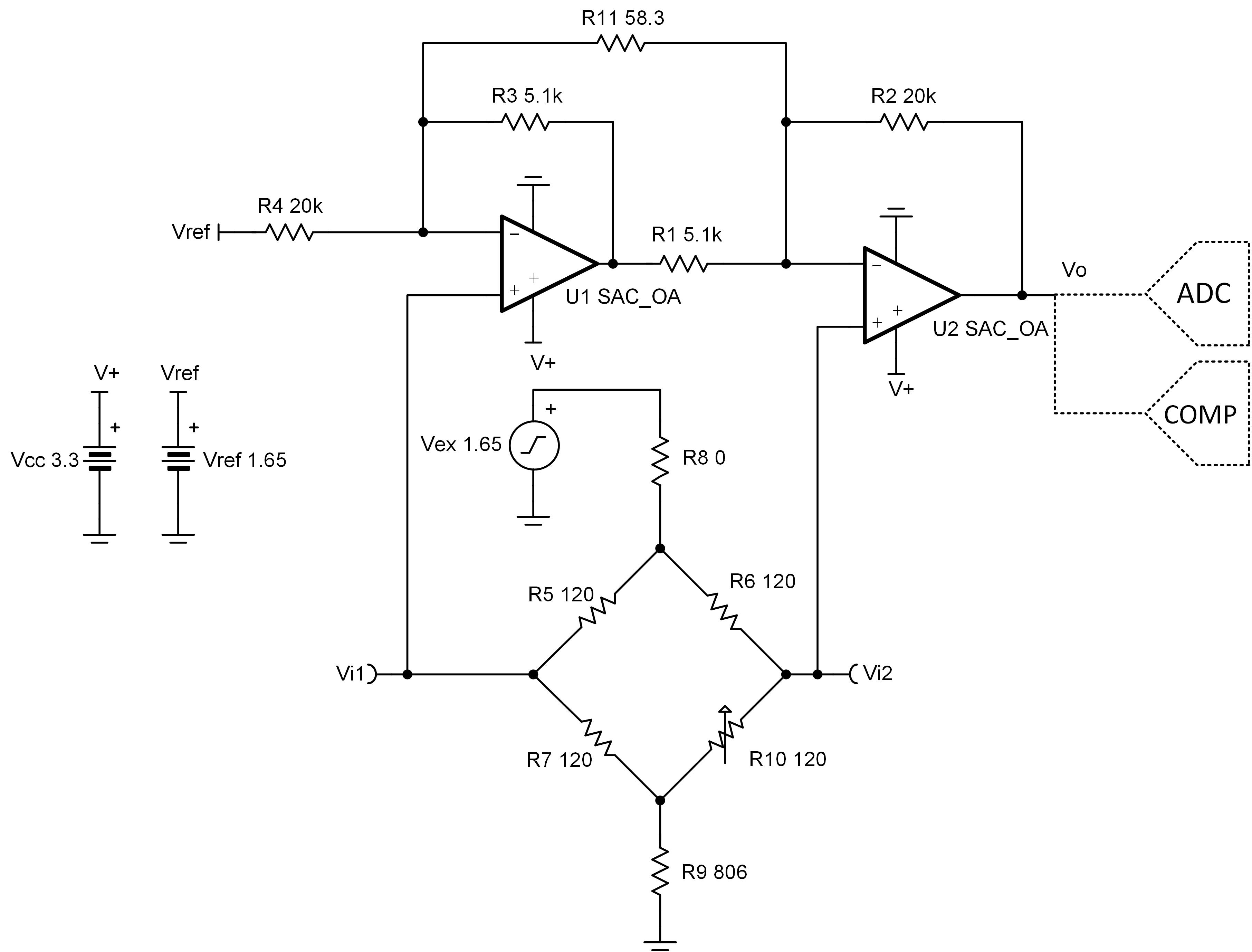
A strain gauge is a sensor whose resistance varies with applied force. The change in resistance is directly proportional to how much strain the sensor is experiencing due to the force applied. This pressure sensing circuit uses a strain gauge placed in a bridge configuration to measure the variation in resistance. This design leverages all four of the built-in op-amp blocks (SACs) in the MSP430FR2355. Two SAC_L3 peripherals are configured in general-purpose mode to amplify a differential signal created by the change in resistance of a strain gauge while the other two are configured in DAC mode to supply the reference voltage (Vref) and the excitation voltage (Vex). By varying R10, a small differential voltage is created at the output of the Wheatstone bridge which is fed to the 2 SAC op-amp instrumentation amplifier inputs. The linearity of the instrumentation amplifier is based on the input common-mode and output-swing ranges of the MSP430 SAC op-amp, which can be found in the specification chart at the end of this document. The output of the second stage op-amp can be sampled directly by the on-board ADC or monitored by the on-board comparator for further processing inside the MCU.
Design Notes
- Resistors R5, R6, and R7 of the Wheatstone bridge must match the stain gauge nominal resistance and must be equal to avoid creating a bridge offset voltage.
- Low tolerance resistors must be used to minimize the offset and gain errors due to the bridge resistors.
- Vex sets the excitation voltage of the bridge and the common-mode voltage Vcm.
- Vref biases the output voltage of the MSP430 SAC-based instrumentation amplifier to mid-supply to allow differential measurements in the positive and negative directions.
- R11 sets the gain of the instrumentation amplifier circuit.
- R8 and R9 set the common-mode voltage of the instrumentation amplifier and limits the current through the bridge. This current determines the differential signal produced by the bridge. However, there are limitations on the current through the bridge due to self-heating effects of the bridge resistors and strain gauge.
- Establish that R1 = R3 and R2 = R4 and that ratios of R2/R1 and R4/R3 are matched to set the Vref gain to 1V/V and maintain high DC CMRR of the instrumentation amplifier.
- Using high-value resistors can degrade the phase margin of the circuit and introduce additional noise in the circuit.
- If the fix is implemented using the MSP430FR2311, the instrumentation amplifier would need to consist of one SAC_L1 op-amp and one Transimpedance Amplifier (TIA) op-amp. The excitation and reference voltages, Vex and Vref, would need to be supplied externally (for example, voltage divider).
- The Strain Gauge Bridge Amplifier Circuit Design Files include code examples showing how to properly initialize the SAC peripherals.
Design Steps
- Select R5,
R6, and R7 to match the stain gauge nominal resistance
- Choose
R9 to set the common mode voltage of the instrumentation
amplifier at 1.34V. WhereTo allow maximum current through the bridge, choose
- Calculate the gain required to
produce the desired output voltage swing
- Select R1,
R2, R3 and R4. To set the Vref gain
at 1V/V and avoid degrading the instrumentation amplifier’s CMRR, R1
must equal R3 and R2 equal R4.
Chooseand
- Calculate R11 to meet
the required gain
- Calculate the current through the
bridge
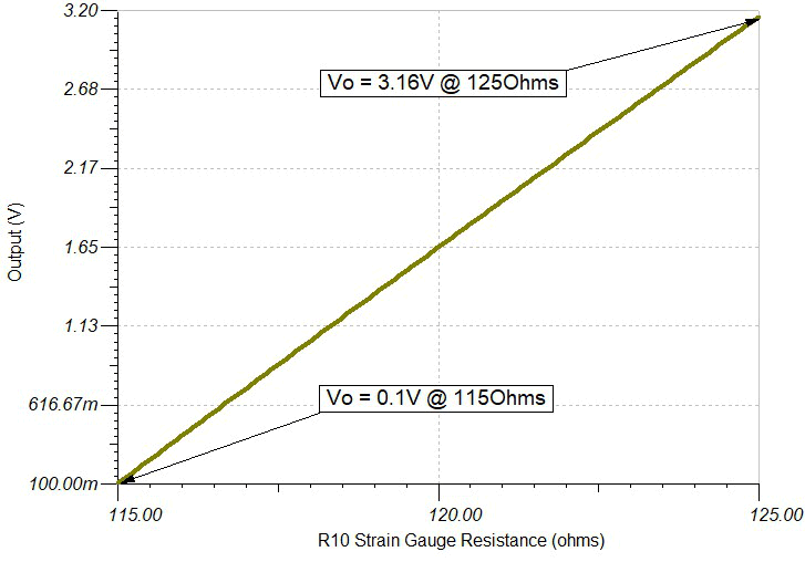
Design Simulations
DC Simulation Results
Target Applications
References
- Texas Instruments, MSP430 Strain Gauge Bridge Amplifier Circuit, code examples and SPICE simulation file
- Texas Instruments, 16MHz Integrated Analog Microcontroller with 3.75KB Fram, OpAmp, Tia, Comparator with Dac, 10-bit ADC, product page
- Texas Instruments, MSP430 MCUs Smart Analog Combo, training video
Design Featured Op Amp
| MSP430FRxx Smart Analog Combo | ||
|---|---|---|
| MSP430FR2311 SAC_L1 | MSP430FR2355 SAC_L3 | |
| Vcc | 2.0V to 3.6V | |
| VCM | -0.1V to VCC + 0.1V | |
| Vout | Rail-to-rail | |
| Vos | ±5mV | |
| AOL | 100dB | |
| Iq | 350µA (high-speed mode) | |
| 120µA (low-power mode) | ||
| Ib | 50pA | |
| UGBW | 4MHz (high-speed mode) | 2.8MHz (high-speed mode) |
| 1.4MHz (low-power mode) | 1MHz (low-power mode) | |
| SR | 3V/µs (high-speed mode) | |
| 1V/µs (low-power mode) | ||
| Number of channels | 1 | 4 |
| MSP430FR2311 | MSP430FR2355 | |
Design Alternate Op Amp
| MSP430FR2311 Transimpedance Amplifier | |
|---|---|
| Vcc | 2.0V to 3.6V |
| VCM | -0.1V to VCC/2V |
| Vout | Rail-to-rail |
| Vos | ±5mV |
| AOL | 100dB |
| Iq | 350µA (high-speed mode) |
| 120µA (low-power mode) | |
| Ib | 5pA (TSSOP-16 with OA-dedicated pin input) |
| 50pA (TSSOP-20 and VQFN-16) | |
| UGBW | 5MHz (high-speed mode) |
| 1.8MHz (low-power mode) | |
| SR | 4V/µs (high-speed mode) |
| 1V/µs (low-power mode) | |
| Number of channels | 1 |
| MSP430FR2311 | |
Related MSP430 Circuits


Trademarks
MSP430™ is a trademark of Texas Instruments.
All trademarks are the property of their respective owners.
IMPORTANT NOTICE AND DISCLAIMER
TI PROVIDES TECHNICAL AND RELIABILITY DATA (INCLUDING DATASHEETS), DESIGN RESOURCES (INCLUDING REFERENCE DESIGNS), APPLICATION OR OTHER DESIGN ADVICE, WEB TOOLS, SAFETY INFORMATION, AND OTHER RESOURCES “AS IS” AND WITH ALL FAULTS, AND DISCLAIMS ALL WARRANTIES, EXPRESS AND IMPLIED, INCLUDING WITHOUT LIMITATION ANY IMPLIED WARRANTIES OF MERCHANTABILITY, FITNESS FOR A PARTICULAR PURPOSE OR NON-INFRINGEMENT OF THIRD PARTY INTELLECTUAL PROPERTY RIGHTS.
These resources are intended for skilled developers designing with TI products. You are solely responsible for (1) selecting the appropriate TI products for your application, (2) designing, validating and testing your application, and (3) ensuring your application meets applicable standards, and any other safety, security, or other requirements. These resources are subject to change without notice. TI grants you permission to use these resources only for development of an application that uses the TI products described in the resource. Other reproduction and display of these resources is prohibited. No license is granted to any other TI intellectual property right or to any third party intellectual property right. TI disclaims responsibility for, and you will fully indemnify TI and its representatives against, any claims, damages, costs, losses, and liabilities arising out of your use of these resources.
TI’s products are provided subject to TI’s Terms of Sale (www.ti.com/legal/termsofsale.html) or other applicable terms available either on ti.com or provided in conjunction with such TI products. TI’s provision of these resources does not expand or otherwise alter TI’s applicable warranties or warranty disclaimers for TI products.
Mailing Address: Texas Instruments, Post Office Box 655303, Dallas, Texas 75265
Copyright © 2024, Texas Instruments Incorporated