SLAA936A September 2020 – March 2021 TAS2563
- Trademarks
- 1Introduction
-
2Quick Tuning Procedure
- 2.1 Initialize Tuning
- 2.2 Flatten Protection
- 2.3 Frequency Response Matching
- 2.4 Microphone Setup
- 2.5 Record Reference Device Response
- 2.6 Set Input Gain
- 2.7 Equalizer
- 2.8 Dynamic Range Compression (DRC)
- 2.9 Smart Amp Protection
- 2.10 Speaker Protection Verification
- 2.11 System Signal Chain
- 2.12 Tuning Elements
- 2.13 PDM MIC
- 3Related Documentation
- 4Revision History
2.8 Dynamic Range Compression (DRC)
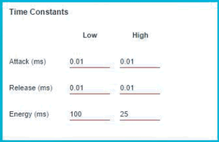
After completing the low-volume tuning, the next step is to incorporate the DRC for mid- to high-volume tuning. On the DRC page, click the enable button at the top right to enable the global DRC function. Next, click on the Crossover button on the right side to reveal the crossover controls. Set the crossover filter and time constant settings as shown in Figure 2-5 and Figure 2-6.
 Figure 2-5 DRC Crossover Filter
 Figure 2-6 DRC Crossover Time Constants
Next, set the compression input and output configuration for each band as shown in Figure 2-7. Do not change the mixer gain or offset—this is a very harsh limiter that prevents most of the high-volume signal from reaching the protection stage. In fact, this limiter effect can be visible with the pink noise in the audio analysis software.
 Figure 2-7 DRC Threshold Control
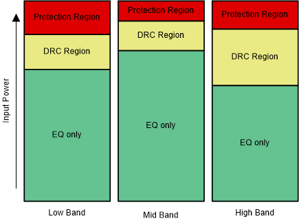
For each band, raise the threshold of region 2 until the response matches the reference device response or ceases to go higher. Now reduce the region 2 threshold again by 5 dB and change the ratio to 5. For region 1, change the ratio to 1.2. The goal is to match the maximum level plot (–6-dB pink noise) to the reference plot for the same level. In the EQ-only region, only 6-dB amplitude intervals occur between each noise track. In the protection region, intervals close to 0 dB occur between each track. Gaps smaller than 6 dB occur in the DRC region. The goal is to try to match these gaps as much as possible.
Figure 2-8 shows an example of the output acoustic pink noise response with the effect of noise floor, DRC, and protection. Figure 2-9 shows the significant power ranges in the audio and the effect of EQ, DRC, and protection.
 Figure 2-8 Acoustic Pink Noise Response
 Figure 2-9 Input Power Regions