SLAA996A June 2021 – June 2021 TPA6304-Q1
- Trademarks
- 1Introduction
- 2Understanding the Thermal Flow
- 3Understanding the Test and System Conditions
- 4Calculating Dynamic Thermal Dissipation
- 5Designing a Realistic Thermal Test
- 6Thermal Tests
- 7Overall Summary
- 8References
- 9Revision History
3.1 Device Efficiency
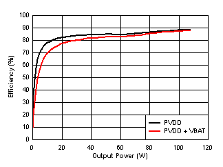
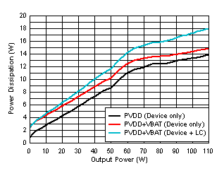
Before designing the thermal solution, its critical to understand what the expected power losses will be from the amplifier. As seen in Figure 3-1 and Figure 3-2, the TPA6304-Q1 is efficient at higher power levels, but the power dissipation is not negligible. More details on the test conditions for these efficiency and power dissipation plots can be found in the TPA6304-Q1 data sheet.
 Figure 3-1 TPA6304-Q1 Efficiency vs Output Power - 4 Ω
 Figure 3-2 Power Dissipation vs Output Power - 4 Ω
Figure 3-2 shows how PVDD, VBAT, and the LC filters change the total power dissipation of the system. For calculating the thermal dissipation into the heatsink, the power loss from the LC filter should be ignored as most systems will have the inductors dissipate their generated heat into the PCB rather than into the heatsink. All of the calculations shown in the rest of this document will be assuming that the heat generated by the inductors will not be dissipated by the heatsink.