SLAAE50A January 2022 – October 2022 MSP430FR2533 , MSP430FR2533
2 Basic Knowledge and Principles of Self-Inductive Capacitive Touch
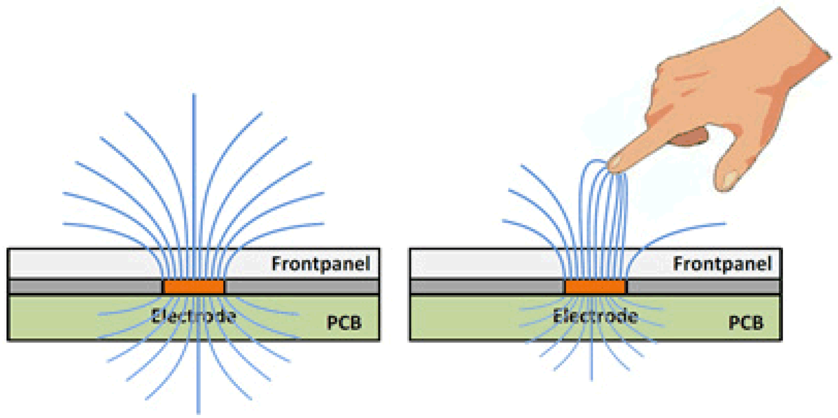
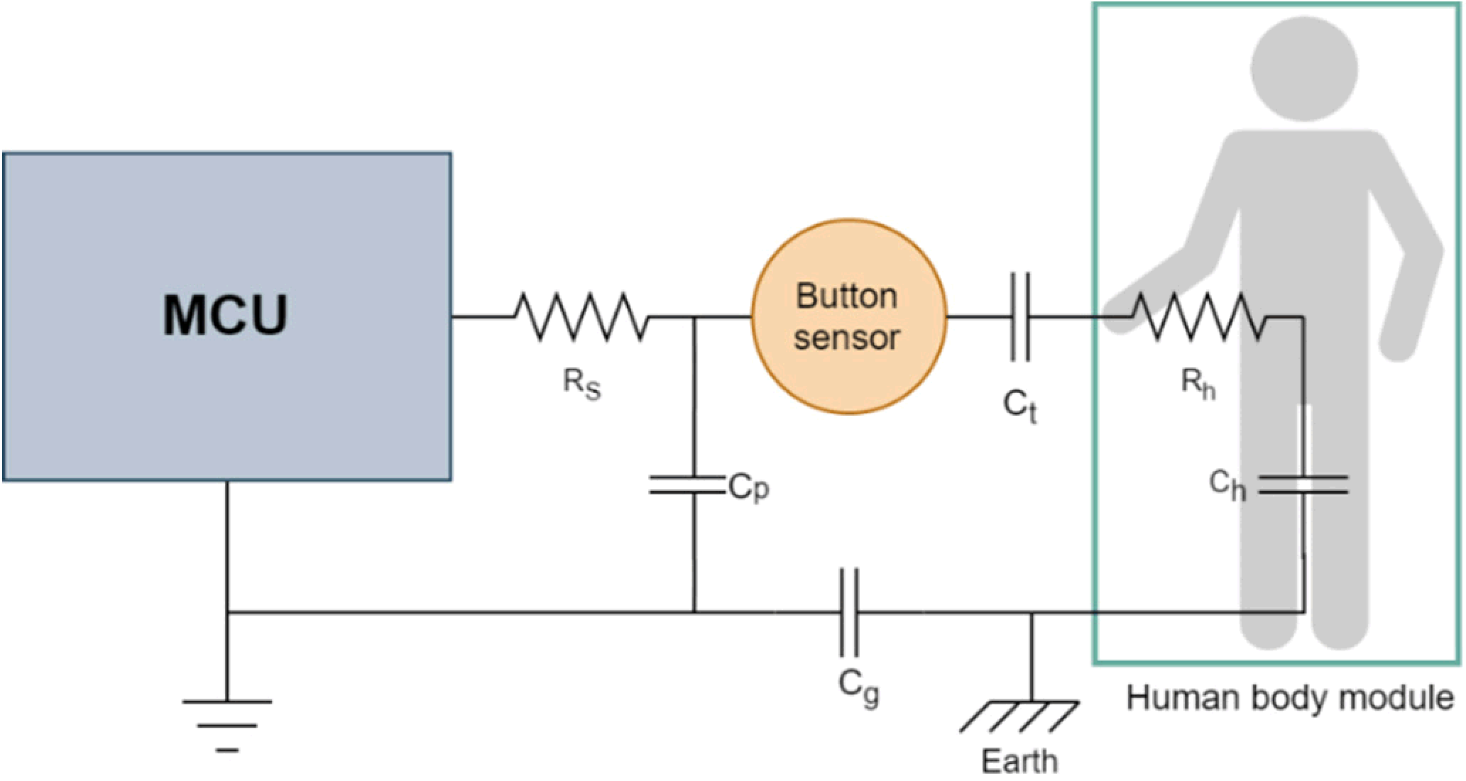
Taking the simplest single button as an example, Figure 2-1 shows a self-inductive capacitor, and Figure 2-2 shows the detection model. The self-inductive capacitor uses a single electrode (receiving electrode Rx) formed by copper coating to detect the change in capacitance of the electrode to the power line ground. The initial capacitance of the button to power line ground is Cp. When a human hand touches it, Ct, Ch, and Cg are introduced into the circuit, thereby increasing the capacitance of the button to ground
 Figure 2-1 Self-Capacitive Detection
 Figure 2-2 Self-Capacitive Detection Model
In Figure 2-2, the solid line indicates the PCB routing, and the dashed line indicates the touch-related routing. Gray components indicate equivalent capacitance or resistance.
Rh = Human body resistance.
Rs = Series resistance. The recommend value is 470 Ω.
Cp = The parasitic capacitance of the button and the connected wire to the power line ground.
Cg = The capacitance between the power line ground and the earth ground. For battery applications, it is approximately 1pF. For grounding applications, it is a short circuit.
Ch = Series capacitance between the human body and the earth ground.
Ct = The capacitance formed by the electrical level and the human fingertip, which is similar to the structure of a parallel plate capacitance.
For ease of analysis, the influence of Rh and Rs is ignored. Equation 1 shows the equivalent capacitance of the button to the power line ground. Sensitivity can be characterized as the ratio between the capacitance change caused by the touch and the base capacitance, as shown in Equation 2. Among them, Ch is larger than Cg and Ct, so it can be ignored.
The parallel plate capacitance is calculated by:
Where:
- A = The contact area between the finger and the sensor pad covering layer.
- d = The thickness of the overlay.
- ε0 = Air dielectric constant.
- εr = The dielectric constant of the overlay.
It can be seen from Equation 2 and Equation 3 that the methods to change the sensitivity are:
- Reduce the thickness of the cover plate to increase the sensitivity.
- Reduce the density of the grid ground, or increase the PCB thickness to reduce the sensitivity.
- Connect the power ground to the earth ground to increase the sensitivity.
- Increase the contact area A between the finger and the sensor pad covering layer to increase the sensitivity.
The electrode size cannot increase indefinitely. The main reason is that the maximum effective area of the parallel plate capacitance Ct is the same as the finger touch area. Therefore, Ct would also increase, resulting in a decrease in sensitivity.
TI's CapTIvate capacitive touch sensing technology is based on charge transfer collection. The operation includes 1) charging the sensor input capacitor Cequal and 2) transferring the accumulated charge to the internal sampling capacitor Csample.
This process repeats until the voltage on both sides of Csample reach the trigger voltage Vtrip of the internal comparator. The number of charge transfers required to reach the threshold directly characterizes the size of Cequal. When the capacitive sensor is touched by a human hand, Cequal and charge transfer values change. The MCU senses the occurrence of a touch event by comparing the numbers of different charge transfer cycles. The MSP430 MCU uses a current mirror to control the proportional relationship between the input current of Csample and the discharge current of Cequal, to equivalently amplify Csample and have a larger range. For self-capacitive detection, Cequal is equal to the capacitance between ground and RX I/O port. Through the charge and discharge to the ground, the electric charge in Cequal is transferred to the internal Csample.
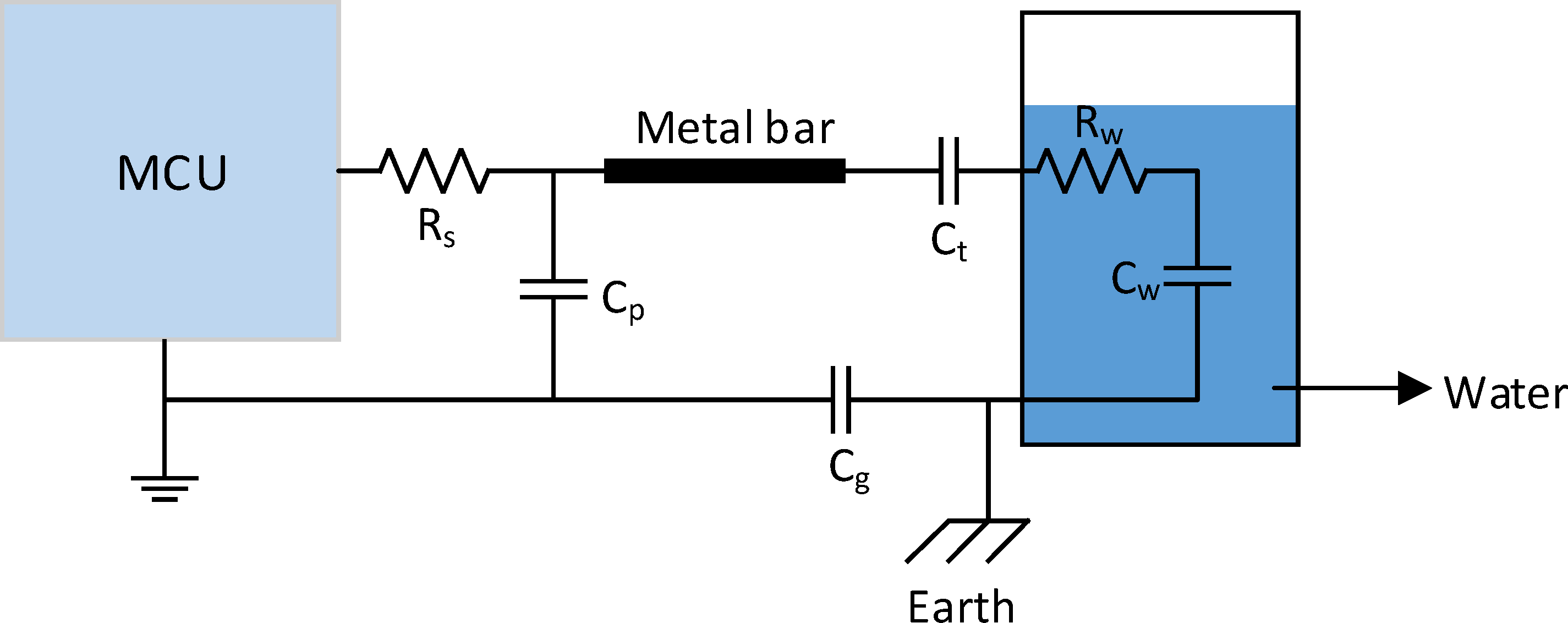
The above is about the change of the capacitance value of the key when the human hand touches the button. Similarly, if the button is replaced by a metal conductor bar, and the human body is replaced by a liquid substance (such as water), it causes the capacitance of the whole metal bar to the ground to change when the water touches the metal conductor bar. The capacitance value of the metal bar to the ground also changes when the water level changes. Through the change in capacitance value, we can determine whether there is water in the object being detected, as well as the depth of the water level. Figure 2-3 shows the detection model.
 Figure 2-3 Liquid Level Detection Model