SLAAEC6A October 2023 – January 2024
- 1
- Description
- Get Started
- Features
- Applications
- 6
- 1Evaluation Module Overview
-
2Hardware
- 2.1 System Overview
- 2.2
Hardware Overview
- 2.2.1 AC-MB Settings
- 2.2.2 TAx5x1xQ1EVM-K Hardware Settings
- 2.2.3 Diagnostics Hardware Setup
- 2.2.4 GPIO1 Hardware Configurations
- 2.2.5 GPO1A Hardware Configurations
- 2.2.6 GPI1A Hardware Configurations
- 2.2.7 GPI2A Hardware Configurations
- 2.2.8 I2C Address Hardware Configurations
- 2.2.9 Audio Serial Interface Hardware Configurations
-
3Software
- 3.1 Software Description
- 3.2 PurePath Console 3 Installation
- 3.3
TAx5x1x-Q1 EVM GUI
- 3.3.1 Software Overview
- 3.3.2 Configuration View
- 3.3.3 End System Integration View
- 3.3.4 Register Map View
- 3.3.5 Preset Configuration
- 3.3.6 I2C Monitor View
- 3.4 Configuration Examples
- 4Hardware Design Files
- 5Additional Information
- 6Revision History
2.2.2.1.1 Line Inputs
For the line input configuration shown in Figure 3-9, the TAx5x1x-Q1 captures the audio signal provided through RCA terminals J2 (IN1), J3 (IN2), header J54, or J55. The RCA white connector is connected to the INxP. The RCA red connector is connected to the INxM. Depending on the differential or single-ended configuration, populate the J6 or J7 jumper as described in Table 3-2 accordingly. The input accepted in this mode is a differential 10-VRMS full-scale audio signal. If a single-ended source is used, the 5-VRMS signal is supported. The gang potentiometer R50 and R51 provide the input bias resistors for this AC-coupled input mode depending on the desired input swing and impedance.
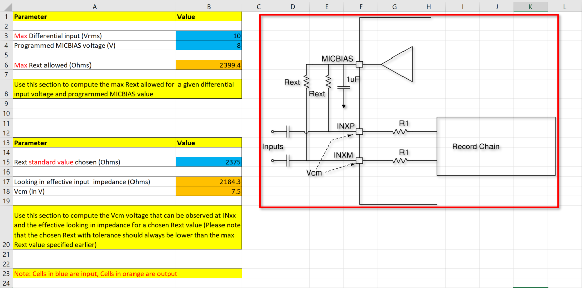
Using the TAx5x1x-Q1 AC-Coupled external resistor calculator, enter the maximum input level and the desired MICBIAS voltage to determine the resistance required to achieve full input swing as shown in Figure 3-11.
From the calculator example below, the maximum resistance allowed is 2399.4 Ohm, and the closest standard resistance is 2375 Ohm. Based on this standard value resistance, the effective impedance looking into the device is about 2184 Ohm. This effective input impedance forms a high pass filter with the external capacitor. The Vcm is the common voltage for the respective MICBIAS and Input Swing. One can adjust the R50 and R51 potentiometer to get the common mode voltage (Vcm). By default, the EVM Vcm is set to 7.3 V.
 Figure 2-11 AC-Coupled External Resistor Calculator