SLAAED3A October 2023 – May 2024 TAA5212 , TAA5242 , TAC5111 , TAC5112 , TAC5142 , TAC5211 , TAC5212 , TAC5242
2.1 Differential AC Coupled Configuration
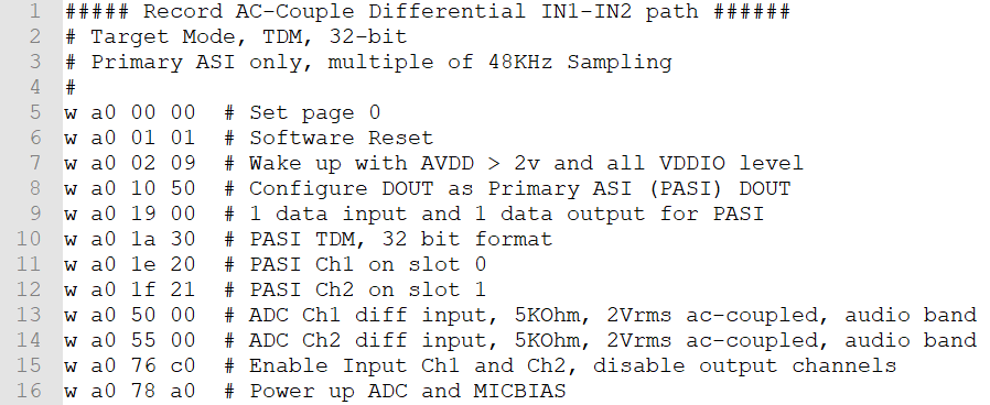
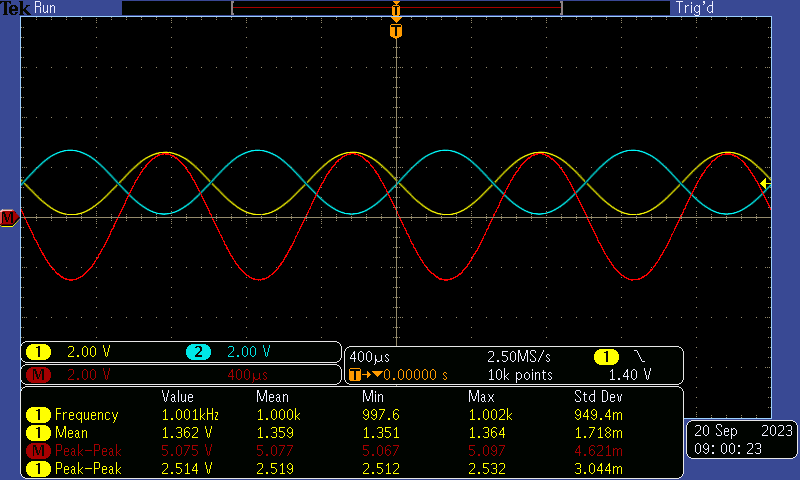
In the AC-Coupled differential input configuration, the following device register setting is used and the respective input waveform provided to IN1P/M for the full-scale swing. Change the register setting in line 13 and 14 for the different input impedance and common-mode tolerance setting B0_P0_R80 (0x50) and B0_P0_R85 (0x55). The following plots are based on Mode 0 with 5KΩ input impedance.
 Figure 2-1 Differential AC-Coupled Register Setting
 Figure 2-2 Differential AC-Coupled Input Swing at -1dBrG (0dBrG = 2Vrms)
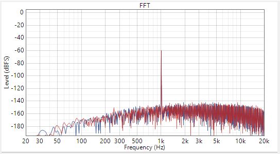
 Figure 2-3 Differential AC-Coupled
Dynamic Range at -60dBrG Input
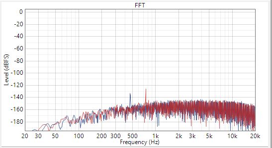
 Figure 2-4 SNR with Input AC Signal
shorted to GND
Figure 2-4 SNR with Input AC Signal
shorted to GNDTable 2-2 summarizes the performances for the three different common tolerances across the input impedance for the different software control device variants. Table 2-3 summarizes the performances for hardware pin control devices which supports 5KOhm input impedance only in differential AC-Coupled.
| DR (dB) | SNR (dB) | THDN (at-1dBrG) | ||||||||
|---|---|---|---|---|---|---|---|---|---|---|
| HCMT Mode | Zin | TAC521x | TAC511x | TAA521x | TAC521x | TAC511x | TAA521x | TAC521x | TAC511x | TAA521x |
| 0 | 5K | 118 | 103 | 118 | 118 | 103 | 118 | -95 | -91 | -95 |
| 10K | 113 | 103 | 113 | 113 | 103 | 113 | -102 | -91 | -102 | |
| 40K | 101 | 103 | 102 | 102 | 103 | 102 | -97 | -91 | -97 | |
| 1 | 5K | 116 | 102 | 116 | 116 | 102 | 116 | -95 | -91 | -95 |
| 10K | 112 | 102 | 112 | 112 | 102 | 112 | -102 | -91 | -102 | |
| 40K | 100 | 102 | 101 | 101 | 102 | 101 | -96 | -91 | -97 | |
| 2 | 5K | 113 | 101 | 113 | 113 | 101 | 113 | -95 | -91 | -95 |
| 10K | 109 | 101 | 109 | 109 | 101 | 109 | -101 | 91 | -101 | |
| 40K | 99 | 101 | 100 | 100 | 101 | 100 | -96 | -91 | -96 | |
| DR (dB) | SNR (dB) | THDN (at-1dBrG) | ||||||||
|---|---|---|---|---|---|---|---|---|---|---|
| MD5-MD4 | Zin | TAC5242 | TAC5142 | TAA5242 | TAC5242 | TAC5142 | TAA5242 | TAC5242 | TAC5142 | TAA5242 |
| 00 | 5K | 117 | 101 | 117 | 117 | 101 | 117 | -95 | -91 | -95 |